RedLINK
TM
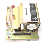
Installation Guide (EIM)
69-2091EFS—07 4
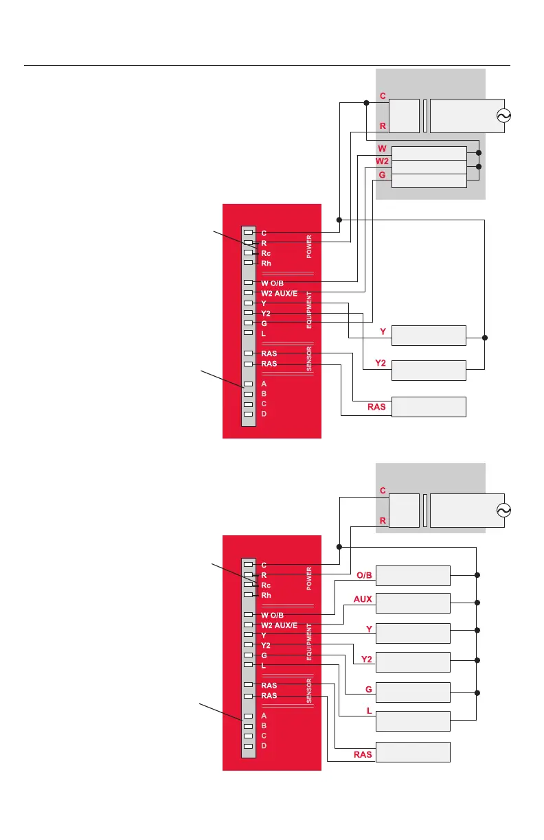
EIM wiring guide
See detailed wiring guides for specific system
types on pages 16-17.
Transformer
24Vac
120Vac
Stage 1 heat
Air Conditioning
Compressor
(Stage 1)
Compressor
(Stage 2)
Return air sensor**
M28470
Stage 2 heat
Fan
Jumper
A/B/C/D UNUSED
(reserved for future use)
EQUIPMENT INTERFACE MODULE
** or C7189U1005 Remote indoor sensor for hydronic
Transformer
24Vac
Changeover
relay
Backup heat
(gas/electric)
Compressor
(Stage 1)
Compressor
(Stage 2)
Fan Relay
M28471
Relay **
Return
Air Sensor
120Vac
Jumper
A/B/C/D UNUSED
(reserved for future use)
** L terminal sends continuous output when thermostat is
set to EmHeat. L terminal is for use with zone panels.
EQUIPMENT INTERFACE MODULE
CONVENTIONAL SYSTEMS
HEAT PUMP SYSTEMS

 Loading...