Model IFP-2100/ECS Installation Manual LS10143-001SK-E
4-35
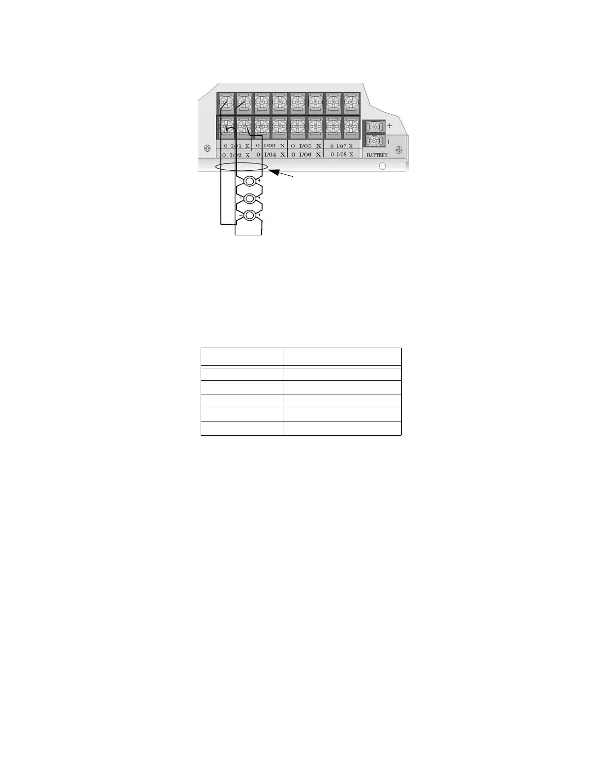
2. Configure the circuit for Class A in programming (see Section 9.5).
Figure 4-48 Class A Notification Appliance Circuit Configuration
Note: In programming any point that uses multiple Flexput circuits, the lowest Flexput circuit number is used to
refer to the circuit pair. For example, Figure 4-48 uses both Flexput circuit 1 and 2, so in programming it
would be referred to as point 1.
Maximum voltage drop is 3V per Class A circuit. See Table 4-5.
4.15.2 Conventional Input Switch Circuits
This section of the manual explains how to install conventional initiating devices for Class A or Class B
configurations.
4.15.2.1 Class B Inputs
You can connect conventional Class B switches, such as waterflow switches and pull stations, directly to the
Flexput circuits of the control panel.
To install a Class B switch:
1. Wire the Class B switch as shown in Figure 4-49.
Table 4-5: Maximum Impedance Class A
Current Maximum Impedance
1.0A 3Ω
1.5A 2Ω
2.0A 1.5Ω
2.5A 1.2Ω
3.0A 1.0Ω
supervised
power limited
regulated 24 VDC
3A per circuit, 9A max combined
 Loading...

