® U.S. Registered Trademark
Copyright © 2001 Honeywell • All Rights Reserved
INSTALLATION INSTRUCTIONS
66- 1106- 2
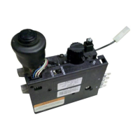
RV8310D,E
Millivolt Receiver/
Modulating Gas Valve
APPLICATION
The RV8310D,E Millivolt Receiver/Modulating Gas Valve
is powered by thermopile generators and has a 60,000
Btuh capacity (1 in. pressure drop for straight-through
configuration). The design makes it ideal for vented
fireplace and space heating applications. The RT8220A
Transmitter is used with this product.
SPECIFICATIONS
Main Gas Connection:
Valve: 3/8 in. NPT thread.
Pilot Gas Connection and Flow:
Connection Size: 7/16-24 UNS.
Flow: 1700 Btuh at 4.0 in. wc pressure drop.
Thermopile Generator:
Q313 with 1/4 in. (6 mm)
quick connect or spade terminals.
Ambient Temperature Range:
0°F to 175°F (-18°C to +79°C).
Pressure Settings:
Natural gas: 3.5/1.7 in. wc typical.
Liquid propane (LP): 10.0/6.3 in. typical.
NOTE: Both high and low settings are fixed.
European Pressure Tap:
For both inlet and outlet
pressure a check can be done by turning a captive
screw and using a plastic tube at the test point.
Voltage:
RV8310D,E: The system uses two Q313 thermopile
generators. Each generator must have a minimum of
500 mV in open circuit under all operating conditions.
Contact Honeywell for test procedure.
Fan Connection:
120 Vac, 50/60 Hz, 2A maximum;
1/4 in. spade terminals.
Approvals:
CSA International certificate
158158-250000102.
Accessories:
396206-1 Natural Gas Conversion Kit.
396206-2 LP GAs Conversion Kit.
INSTALLATION
When Installing this Product...
1.
Read these instructions carefully. Failure to
follow them could damage the product or cause
a hazardous condition.
2.
Check the ratings given in the instructions and on
the product to make sure the product is suitable for
your application.
3.
Installer must be a trained, experienced service
technician.
4.
After installation is complete, check out product
operation as provided in these instructions.
WARNING
Oxygen Depletion Hazard.
Can cause injury or death due
to asphyxiation.
Use only vented gas valve models on vented
appliances. Use only unvented gas valve models
on unvented appliances.
WARNING
Fire or Explosion Hazard.
Can cause property damage,
severe injury or death.
Follow these instructions exactly:
1.
Turn off gas supply at the appliance service
valve before starting installation, and perform
a Gas Leak Test after the installation is
complete.
2.
Always install the sediment trap in the gas
supply line to prevent contamination of the
gas valve.
3.
Do not force the gas valve control knob.
Use only your hand to turn the control knob.
If the knob does not operate by hand, the
valve should be replaced by a qualified
service technician.