Do you have a question about the Honeywell RXSW100A3CULH and is the answer not in the manual?
Welcomes the user and emphasizes proper maintenance for performance and longevity.
Manufacturer cannot anticipate all hazards; verify procedures are safe and do not render equipment unsafe.
Explains DANGER, WARNING, CAUTION, and NOTE symbols used in the manual for hazard communication.
Details dangers of electrocution, backfeed, and equipment damage due to electrical issues.
Covers general risks like electrical backfeed, jewelry while working, and automatic start-up hazards.
Instructions for carefully unpacking the transfer switch and inspecting for shipping damage.
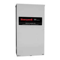
Describes the automatic transfer switch's purpose, components, and suitability for standby systems.
Explains the single-phase mechanism, neutral line connection, and conductor size range.
Details specifications for utility service and generator disconnect circuit breakers for 100 and 200 amp models.
Explains the importance of the data decal for switch limits and ordering information.
Describes the UL/CUL type 3R enclosure and its protection against weather elements.
Emphasizes reading manual, safety rules, and labels before installation, operation, or servicing.
Introduces load management systems like SACM and SMM for generator overload prevention.
Explains how SACM manages air conditioner loads by shedding them during generator overload.
Describes SMM for managing various loads, accommodating up to eight individual SMMs.
Discusses how SACM and SMM can be used together and shared priorities for load management.
Outlines main procedures for installing the transfer switch, including mounting and wiring.
Provides guidance on mounting enclosure vertically to a rigid structure and ensuring it is level.
Detailed steps on how to safely remove outer and inner panels of the enclosure.
Instructions for connecting utility supply, generator, and load leads to appropriate terminals.
Guides on connecting generator control wiring, including wire gauge and length considerations.
Instructions on connecting SACM to control air conditioner loads via thermostat signals.
Details how to connect and control air conditioners using SACM terminals and contact ratings.
Explains use of normally-closed auxiliary contact for customer accessories or remote devices.
Describes requirement for field marking short-circuit current rating on enclosure for NEC compliance.
Guides on performing functional tests after installation, emphasizing adherence to manual's order.
Instructions on how to manually operate the transfer switch, including important safety warnings.
Steps for manually moving switch to connect to utility power source.
Steps for manually moving switch to connect to generator power source.
Steps for manually returning switch to utility power source position.
Guidance on performing voltage measurements using DMM with LowZ setting for accuracy.
Steps to verify correct voltage levels from utility supply before proceeding.
Procedures to check generator voltage and frequency after stabilization and before connecting to switch.
Steps for testing generator's performance when powering electrical loads.
Procedures to verify system's automatic transfer sequence from utility to generator and back.
Final verification of installation, compliance, and educating end-user on operation.
Steps for safely shutting down generator, especially during utility outages or under load.
Safety warnings and steps for preparing unit before performing maintenance, including turning off power.
Instructions on how to use test button on SACM to simulate overload and check load shedding.
Information on accessing and replacing fuses for SACM, including tool usage and fuse specifications.
Refers to SMM manual for testing procedures, indicating SMM is a separate component.
Provides dimensional and mounting information for the transfer switch enclosure.
Illustrates how transfer switch connects to utility supply, generator, and load distribution panel.