S8600B,C,H,M; S8610B,C,H,M; S8670D,E,J,K INTERMITTENT PILOT GAS IGNITION CONTROL
บริษัท เอดีดี เฟอร์เนส จํากัด
ADD FURNACE CO.,LTD.
44 ซอยบรมราชชนนี 70 ถนนบรมราชชนนี แขวงศาลาธรรมสพน์ เขตทวีวัฒนา กรุงเทพฯ 10170
โทร: 02-888-3472 โทร: ออกแบบ:08-08-170-170 แฟกซ์: 02-888-3258
https://www.add-furnace.com E-mail: sales@add-furnace.com
Table 7. Lockout Models B, H D, and J Only—Green LED Status Codes. (Continued)
Recommended Service Action
Flame rod shorted to ground
Control remains in wait mode. When the fault
corrects, control resumes normal operation.
Check flame sense lead wire for damage or
shorting. Check that flame rod is in proper
position.Check flame rod ceramic for cracks,
damage or tracking.
Low secondary voltage supply
Control remains in wait mode. When the fault
corrects, control resumes normal operation.
Check transformer and AC line for proper
input voltage to the control. Check with full
system load on the transformer.
a
Flash Code Descriptions:
-
Flash Fast: rapid blinking.
-
Heartbeat: Constant ½ second bright, ½ second dim cycles.
-
4 second solid on pulse followed by “x” 1 second flashes indicates flame current to the nearest
A. This is only
available in run mode.
-
A single flash code number signifies that the LED flashes X times at 2Hz, remains off for two seconds, and then
repeats the sequence.
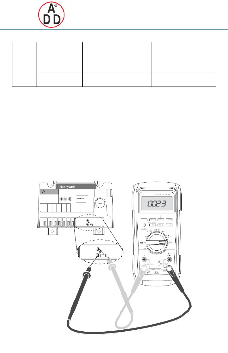
Flame Current Measurement
Flame current of the device can be meaured using a
standard micro-ammeter by simply inserting the meter
probes into the holes labeled FLAME CURRENT, as
shown in Fig. 13.
—
Flame current must be measured with pilot valve
lit but no main gas flowing.
—
Disconnect MV leadwire from the control before
measuring flame current.
—
Set meter to DC
Amp scale.
—
Ensure meter leads are positioned correctly [+/-].
NOTE: Trying to measure the pilot flame current in
series with the wiring will not be accurate.
Recommended Minimum Pilot Only Flame Current:
•
Must read steady 1
Amp DC minimum.
•
Flame current should be 2
Amp or greater for reliable
appliance operation.
Fig. 13. Measuring pilot flame current with micro-ammeter.
Golde n Valley, M N 55422
Asse mbled in M exico
!
WARNING 24V, 60 Hz; PV=1A Max.; MV=1A Max.
Explosion Hazard.
Can cause serious injury or d eath.
This device can malfunction if
LED FLAM E INDICATION:
90 Sec. Trial for Ignition
- 4 sec. pulse then 1 sec. flashes
indicate flame c urrent in uA:
®
it gets wet. Never try to use a
= 3 uA
- Ensure 1 uA to kout
C US
device that has been wet - replace it.
5004 3739- 003
Rev.
A
ANSI
Z21. 20
LED FLASH CO DES:
(2)
retry
(3)
recycle
(4)
flame out of sequence
(6)
internal err or
(7)
flame ro d shorted
(8)
low input voltage
+
FLAME
CURRENT
– STATUS
+
FLAME
 Loading...


