69-2042—01 2 69-2042—01 3 69-2042—01 4 69-2042—01 5
TECHNICIAN’S QUICK REFERENCE GUIDE
69-2042-01
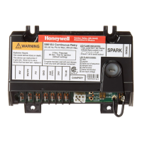
S8610U Universal
Intermittent Pilot Gas
Ignition Control
The following service procedure provides a quick overview for
the S8610U series control. For more information, refer to form
69-1955.
Fig. 1. Typical wiring connections.
SETTINGS AND ADJUSTMENTS
DIP Switch (S1) Settings
When replacing an existing ignition control with the S8610U,
refer to 69-1955 for the correct DIP switch settings.
IMPORTANT
Do not power the ignition control prior to setting
the DIP switches.
The following timing parameters may be set with this 2-position
DIP switch.
Prepurge
To select Prepurge, set SW1 according to Table 2.
Trial for Ignition (TFI)
To select the Trial for Ignition timing, set SW2 according to
Table 2.
Fig. 2. DIP Switch (S1) Location.
Fig. 3. DIP Switch (S1) - shown with factory default
settings (OFF) for SW1 and SW2.
LED STATUS AND
TROUBLESHOOTING
The ignition control module has one LED used for flame
sensing and system status.
Fig. 4. Location of LED.
SPARK
MV
24V GND
MV/PV
PV
BRN/GND
REMOTE
SENSE
TH-W (OPT.)
24V (OPT.)
M29890
SENSE
JUMPER
WIRE
P1 VENT DAMPER
CONNECTOR
Table 1. Typical Wiring Connections.
Connector
Label
Size or
Type Description
MV 1/4 inch Main Valve connection
MV/PV 1/4 inch Common terminal for gas valves
PV 1/4 inch Pilot Valve connection
BRN GND 1/4 inch Burner Ground
24V GND 1/4 inch Return path to transformer
24V 1/4 inch Optional—
24 Vac power connection for Vent
Damper
TH-W 1/4 inch Connector for “Call for Heat” signal
from thermostat
P1 6-pin
keyed plug
Connector for Vent Damper
connection (used to control a
connected damper in atmospheric
appliances)
METER (μA) Ammeter
probes
Connection for ammeter probes for
measuring flame current in μAmp DC.
SENSE
JUMPER
WIRE
Wire with
3/16 inch
quick
connect
Connects to the REMOTE SENSE
connector for installations with a single
spark rod (local flame sensing)
NOTE: For installations with remote
flame sensing (separate spark and
sensor rods), this jumper wire is
clipped as close to the circuit board as
possible and the wire is discarded.
REMOTE
SENSE
3/16 inch Flame Sensor connector
For single rod installations, connect
the SENSE JUMPER WIRE to this
terminal connector.
For dual rod installations, connect the
flame sense wire from the burner/
igniter to this terminal connector.
SPARK 1/4 inch High voltage sparking electrode
Table 2. DIP Switch (S1) Settings.
Prepurge Trial For Ignition SW1 SW2
None 90 seconds OFF OFF
30 seconds 90 seconds ON OFF
None 15 seconds OFF ON
30 seconds 15 seconds ON ON
M29894
S1 DIP SWITCH
ON
12
S1
M23587