3
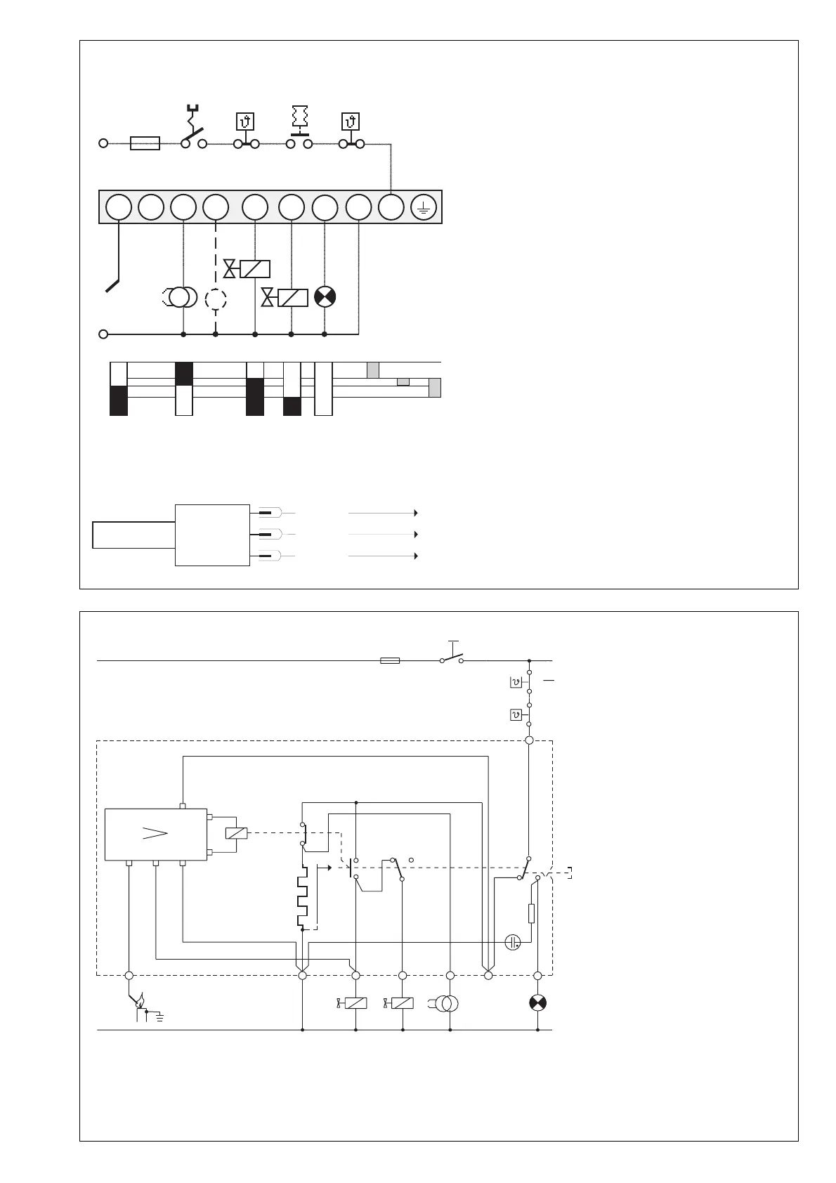
HS Main switch ST Safety thermostat
RT Controlling thermostat RF Flame relay
B Thermal timing unit V1 Valve1
R26 Resistor V2 Valve 2
Ion Ionisation probe SA Lockout indicator
ZT Ignition > Amplifier IV7
WIRING AND SEQUENCE DIAGRAMS TFI 812.2
IRD CONNECTION
GENERAL CIRCUIT DIAGRAM TFI 812.2
HS Main switch
GW Gas proving switch
ST Safety thermostat
RT Controlling thermostat
IS Ionisation probe
Z Ignition
V1 Solenoid valve, 1st stage
V2 Solenoid valve, 2nd stage
SA remote lockout indicator
M Auxiliary blower
tw Pre-ignition time
approx. 15 sec. (mod. 5)
approx. 10 sec. (mod. 10)
ts Safety time nominal 5 sec. (mod. 5)
10 sec. (mod. 10)
tv2 2nd stage delay approx. 20 sec.
blue
black
brown
Kl. 8
Kl. 1
Kl. 9
IRD
1020.1
TFI 812
RF
R26
1
Ion
9
RT
ST
HSPh
B
s
v1
b
z
365748
ZTV2V1
SA
N
SA
Z
V1
IS
M
V2
SA
10A max.
HS
ST
GW
RT
Ph
N
1234 5 6789
tw ts tv2
10A fast
6A slow

 Loading...