34-ST-25-63 RMA801 Quick Start Guide 1
SmartLine RMA801 HART/DE Remote Indicator Assembly
Quick Start Installation Guide
34-ST-25-63, Revision 7, February 2022
This document provides descriptions
and procedures for the Quick
Installation of Honeywell’s family of
SmartLine Remote Indicator.
The SmartLine Remote Indicator is a
configurable intelligent field device
which functions as an output and
status indicator for any HART and
DE devices.
For full details refer to the manuals
listed below for protocols, user
Interface (HMI) operation, Installation,
configuration, calibration,
maintenance, parts, and safety and
approvals etc. including options
Copyrights, Notices and
Trademarks.
Copyright 2021 by Honeywell
Revision 7, November 2021
Trademarks
SmartLine, RMA are U.S.
registered trademarks of
Honeywell Inc.
HART® is Trademarks of Field
COMM Group™
Table of Contents
Installation and setup........................................................................... 1
Site evaluation......................................................................... 1
Installation precautions ........................................................... 1
Explosion-Proof Conduit Seal ............................................................. 1
Mounting Remote indicator ................................................................. 2
Mounting Dimensions .......................................................................... 2
Bracket Mounting ................................................................................. 2
Wiring a Remote Indicator ............................................................. 2
Terminal Block ........................................................................ 2
Wiring Connections and Power Up ............................................... 3
Wiring Options......................................................................... 3
DEVICE CONFIGURATION ................................................................ 3
Appendix A. PRODUCT CERTIFICATIONS ....................................... 3
Figure 1: Electronics Housing Components ........................................ 1
Figure 2: Typical Pipe Mounted Installations ...................................... 2
Figure 3: Pipe Mount - Horizontal Mounting Bracket .......................... 2
Figure 4: Pipe Mount - Vertical Mounting Bracket .............................. 2
Figure 5: Remote Indicator Secured to a Wall Mounting Bracket ....... 2
Figure 6: DE/ANALOG Terminal Block ............................................. 23
Figure 7: RMA801 Terminal Block ...................................................... 2
Figure 8: Remote Indicator connected to the negative loop wire ....... 3
Figure 9: Remote Indicator connected to the negative loop wire ....... 3
Figure 10: Remote Indicator connected to the positive loop wire ....... 3
Documentation
To access complete documentation, including language variants, scan
the QR code below using your smart phone/device or QR code scanner.
Go to the APP store for your free Smartphone QR scanner
Or you can follow the URL to access the online SmartLine HUB page.
The HUB page will contain direct links to open SmartLine product
documentation.
URL QR Code
https://hwll.co/SmartLineHUB
Features and Options
The RMA801 Remote Indicator provides a means of remote-mounting a indicator
(display) that is associated with a Honeywell Smartline Transmitter or any
transmitter operating in a 4-20 mA current loop.
The RMA801 is a DE/Analog Remote Indicator which can be connected anywhere
along the current loop.
For analog PV, the RMA801 measures the loop current and displays the equivalent
PV value on the display.
The RMA801 will auto configure when connected to Honeywell DE transmitters
except SMV800/3000when a database upload is performed.
This document provides the information for a quick setup. For detailed information,
please refer RMA801 user manual, 34-ST-25-62.
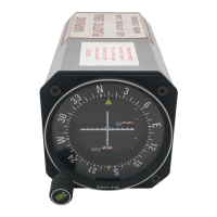
Figure 1: Electronics Housing Components
CAUTION
Temperature extremes can affect display quality. The display can go blank if the
temperature is below -20°C or above 70°C; however, this is only a temporary
condition. The display will again be readable when temperatures return to within
operable limits.
The device shall be operated by a trained professional. It is the user/installer’s
responsibility to install the indicator in accordance with national and local code
requirements. Conduit entry plugs and adapters shall be suitable for the
environment, shall be certified for the hazardous location when required and
acceptable to the authority having jurisdiction for the plant
The RMA device is always connected in series with the transmitter. The current
loop will be broken if the RMA801 device is removed from the loop.
Installation and setup
Site evaluation
Evaluate the site selected for the Remote Indicator installation with respect to
the process system design specifications and Honeywell’s published
performance characteristics for your particular model. Some parameters that you
may want to include in your site evaluation can be found in the RMA801 user
manual,
#34-ST-25-62
Installation precautions
Temperature extremes can affect display quality. The display can go blank if the
temperature is below -20°C or above +70°C; however, this is only a temporary
condition. The display will again be readable when temperatures return to within
operable limits.
Explosion-Proof Conduit Seal
When installed as explosion proof in a Division 1 Hazardous Location, keep
covers tight while the Remote Indicator is energized. Disconnect power to
the Remote Indicator in the non-hazardous area prior to removing end caps for
service.
When installed as non-incendive equipment in a Division 2 hazardous location,
disconnect power to the Remote Indicator in the non-hazardous area, or
determine that the location is non-hazardous before disconnecting or
connecting the Remote Indicator wires.