34-ST-25-63 RMA801 Quick Start Guide 2
Mounting Remote indicator
Summary Remote Indicator models can be attached to a two-inch (50.8 millimeter)
vertical or horizontal pipe using Honeywell’s optional pipe mounting bracket.
Honeywell’s optional wall mounting bracket is also shown in figures below.
Mounting Dimensions
Refer to Honeywell drawing number 51455045
*
for detailed electronic housing
dimensions. Refer to Honeywell drawing numbers 32306827
*
for detailed pipe
mounting dimensions, 50124813
*
for Detailed Pipe Angle mounting dimensions and
32306828
*
for detailed wall mounting dimensions.
THE TRANSMITTER ENCLOSURE CAN BE ROTATED A TOTAL OF 90° FROM
THE STANDARD MOUNTING POSITION.
* Honeywell drawings can be supplied on request.
Bracket Mounting
If you are using an optional bracket, start with Step 1.
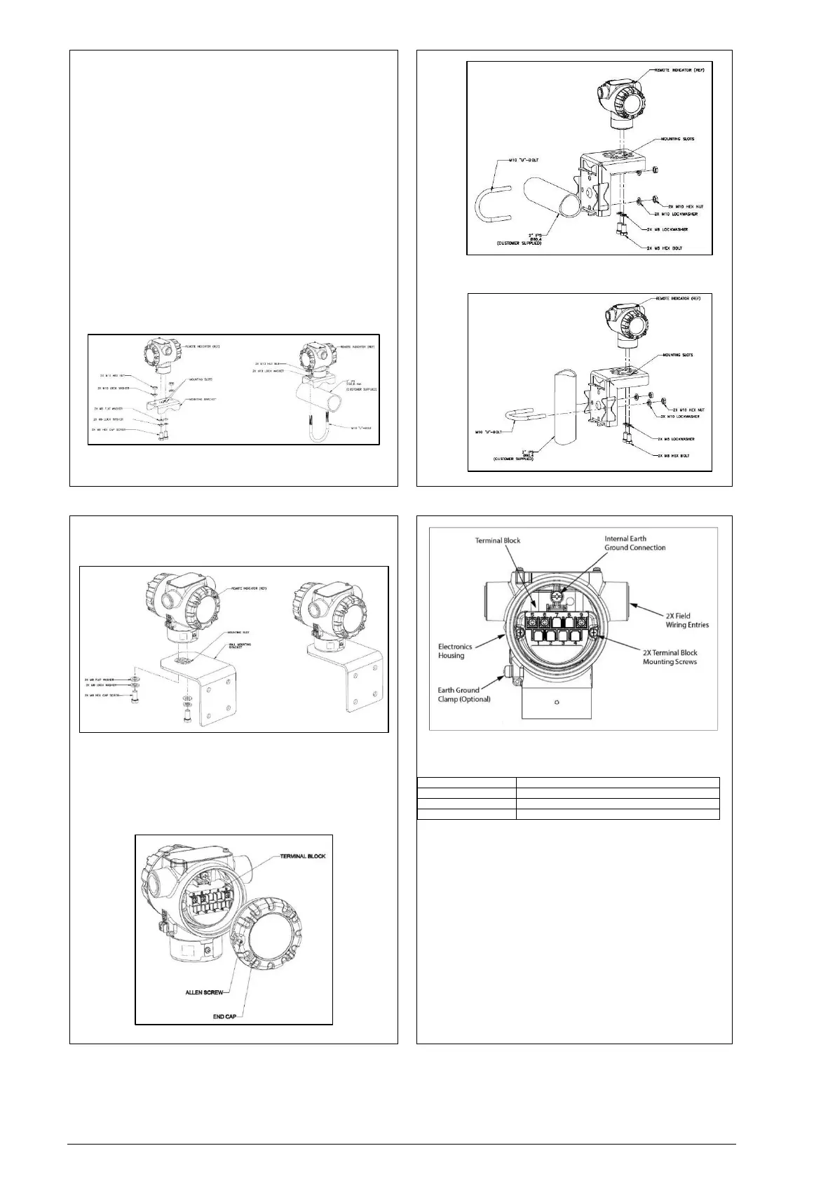
1. Pipe Mount Option -Refer to Figure 2, Figure 3 and Figure 4. Align the
two mounting holes at the bottom of the Remote Indicator with the two
slots in the mounting bracket and assemble the (2) M8 hex cap
screws, (2) lock washers and (2) flat washers provided.
2. Rotate the Remote Indicator assembly to the desired position and
torque the M8 hex cap screws to 27,0 Nm/20,0 Lb-ft maximum.
Position the bracket on a 2-inch (50.8 mm) horizontal or vertical pipe and
install a “U” bolt around the pipe and through the holes in the bracket. Secure
the bracket with (2) M10 hex nuts, (2) flat washers and (2) lock washers
provided. Refer to Figure 4.
Figure 2: Typical Pipe Mounted Installations
Figure 3: Pipe Mount - Horizontal Mounting Bracket
Figure 4: Pipe Mount - Vertical Mounting Bracket
3. Wall Mount Option – Refer Figure 5 Position the bracket on the
mounting surface at the desired location and secure the bracket to the
mounting surface using the appropriate hardware (Wall mounting
hardware requirements to be determined and supplied by the end
user).
Figure 5: Remote Indicator Secured to a Wall Mounting Bracket
Wiring a Remote Indicator
Overview
The Remote Indicator is designed to operate in normal 4-20mA analog mode with
HART enabled transmitters across Smartline Devices and DE transmitters except
SMV800/3000.
For improved noise performance, it is recommended to provide earth ground for
both transmitter and RMA housing.
Figure 6: DE/ANALOG Terminal Block
Figure 7: RMA801 Terminal Block
Terminal Block
The RMA801 has 3 terminals. Following table provides the connection details-
Three screw terminals suitable for wirings up to (16AWG)
• Shielded, twisted-pair cable such as Belden 9318 or equivalent must be
used for all signal/power wiring.
• The cable shield must be connected at only one end of the cable.
Connect it to the power supply side and leave the shield insulated at
the transmitter side and RMA side.
Note: If solid core wire is used strip insulation 1/4 in (6 mm). Once inserted
under the square washer the stripped portion should be contained under the
square washer. If multi-stranded wire is used, a ferrule is to be used and the
stripped wire should be in the insulated portion of the ferrule. The ferrule can be
also be used on the solid core wire.
Loop Terminals 5 & 6 shall be connected in series with the 4-20 ma loop for both
analog and DE modes. Additionally, third wire (Terminal 9) is required for DE
communication in DE mode only.
Loop wiring for analog and DE mode is shown in figure below.
NOTE: After wiring the Transmitter as outline in the next sections, torque
the screws to 1.1 Nm (10 lb-in)
 Loading...