SPYDER® BACNET® PROGRAMMABLE CONTROLLERS
63-1328—05 6
* Refer to the PICS (Protocol Implementation Conformance Statement) for complete details.
Accessories
— TR70, TR70-H Zio LCD Wall Module
— 201052A,B,C Auxiliary Switches (one, two or three
switches)
— C7041B,C,D,P,R Air Temperature Sensor (indoor)
— C7770A Air Temperature Sensor (indoor/plenum)
— C7031G Air Temperature Sensor (outdoor)
— C7041F Air Temperature Sensor (outdoor)
— TR23 Wall Module
— C7400A Enthalpy Sensor
— P7640 Pressure Transducer Family
— C7232 CO
2
Sensor Family
— C7600 Humidity Sensor Family
— H7625, H7635, and H7655 Humidity and Temperature
Sensors
Refer to the “Sensors Product Overview,” form 63-9285, for
additional accessories.
Mounting
The controller enclosure is constructed of a plastic base plate
and a plastic factory-snap-on cover. The cover does not need
to be removed from the base plate for either mounting or
wiring. Removable terminal blocks are used for all wiring
connections, which allow the controller to be wired before or
after mounting.
The controller can be mounted in any orientation. Ventilation
openings are designed into the cover to allow proper heat
dissipation, regardless of the mounting orientation.
NOTE: The controller must be mounted in a position that
allows clearance for wiring, servicing, and
removal.
NOTE: For complete mounting information, refer to the
Installation Instructions, form 62-0310.
PVBXXXXAS Mounting (Controllers with
actuators)
The PVBXXXXAS controllers include the direct-coupled
actuator with Declutch mechanism, which is shipped
hard-wired to the controller (using digital outputs 7 and 8).
The actuator mounts directly onto the VAV box damper shaft
and has up to 44 lb-in. (5 Nm) torque, 90-degree stroke, and
90 second timing at 60 Hz. The actuator is suitable for
mounting onto a 3/8 to 1/2 in. (10 to 13 mm) square or round
VAV box damper shaft. The minimum VAV box damper shaft
length is 1-9/16 in. (40 mm).
After the actuator is mounted to the damper shaft, the
controller mounts to a panel by using four No. 6 or No. 8
machine or sheet metal screws inserted through the corners
of the base plate.
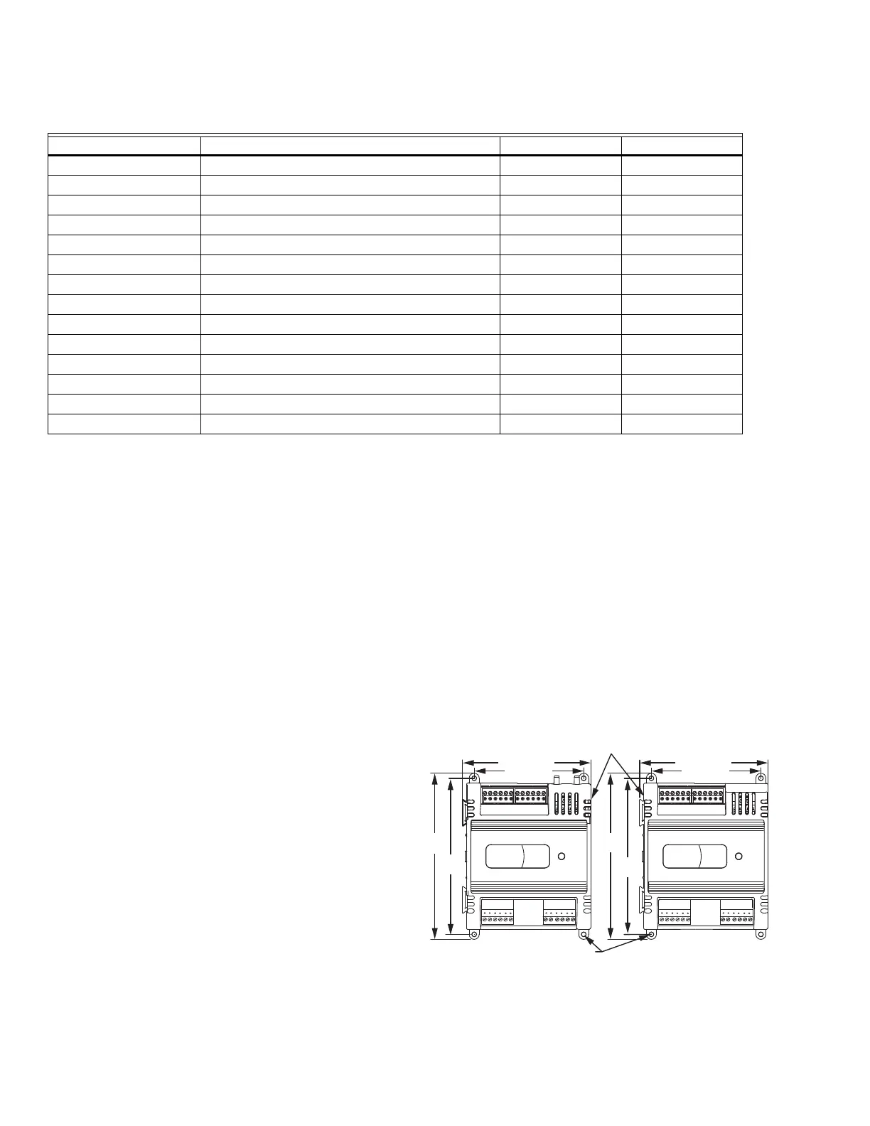
Fig. 1. Panel mounting—controller dimensions in inches
(mm) for PUB1012S, PUB4024S, and PVB4024NS only
(PUB4024S and PVB4024NS shown).
Table 5. BACnet Interoperability Building Blocks (BIBBs) Supported.*
BIBB Service Initiates Responds to
DS-RP-A/B ReadProperty XX
DS-RPM-B ReadPropertyMultiple X
DS-WP-A/B WriteProperty XX
DS-WPM-B WritePropertyMultiple X
DM-BR-B AtomicReadFile X
DM-BR-B AtomicWriteFile X
DM-BR-B ReinitializeDevice X
DM-DDB-A/B Who-Is XX
DM-DDB-A/B I-Am XX
DM-DOB-B Who-Has X
DM-DOB-B I-Have X
DM-DCC-B DeviceCommunicationControl X
DM-TS-B TimeSynchronization X
DM-UTC-B UTCTimeSynchronization X
M33228
NOTE: CONTROLLER CAN BE MOUNTED IN ANY ORIENTATION.
3/16 (4.5) PANEL MOUNTING HOLE (4X)
1 1 1 1 1 1 1 2 2 2 2 2
3 4 5 6 7 8 9 0 1 2 3 4
1 1 1 1 1 1 1 2 2 2 2 2
3 4 5 6 7 8 9 0 1 2 3 4
1 2 3 4 5 6
DEPTH IS 2-1/4 (57)
4-13/16 (122)
4-1/8 (105)
6-1/4
(159)
5-7/8
(149)
4-13/16 (122)
4-1/8 (105)
6-1/4
(159)
5-7/8
(149)
7 8 9
10 11 12
1 2 3 4 5 6
7 8 9
10 11 12

 Loading...


