2 ST9100A, ST9100C Timers Installation Guide 3
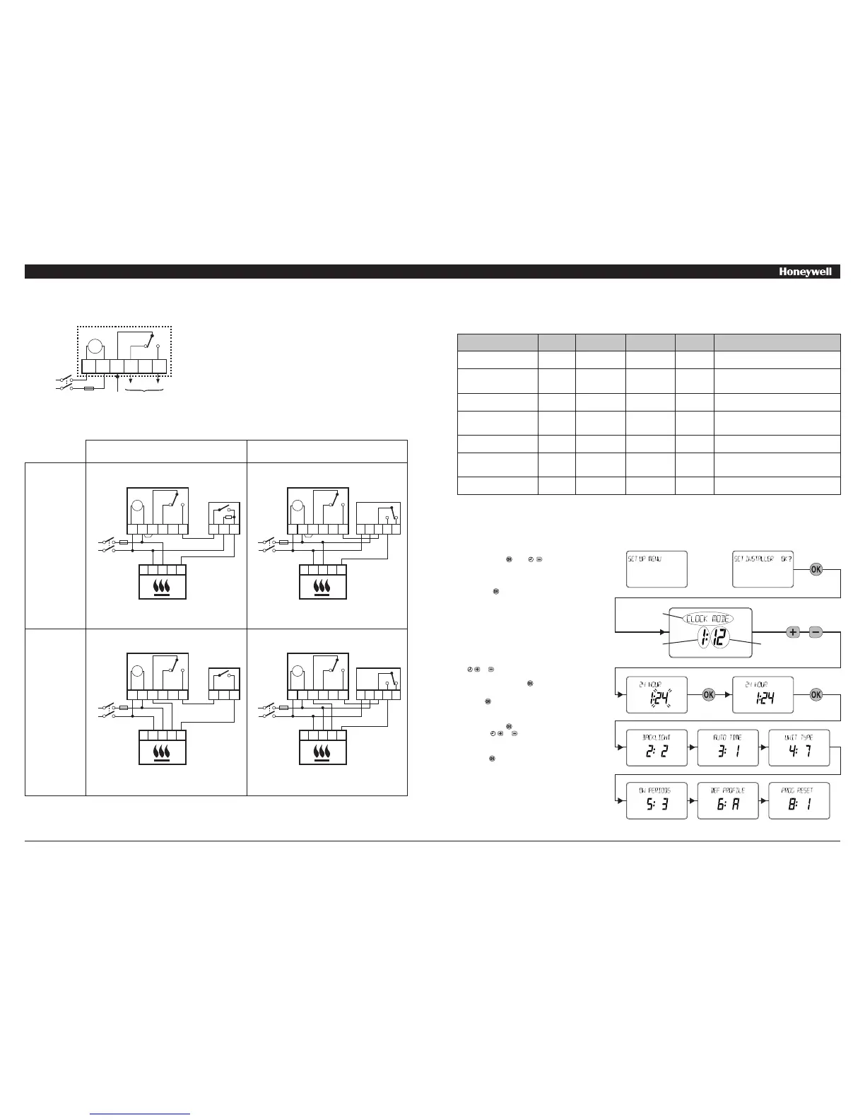
WIRING CONNECTIONS
ST9100 Internal Wiring
Notes
1. ST9100 is suitable for contact-closure potential free or mains voltage
switching
2. If normal mains voltage is required, link terminals L and 1.
3. The ST9100 is a Class II (double insulated) device. A parking
terminal is provided for earth wiring continuity, if required.
4. Where applicable, the ST9100 may also be used to control hot water
systems independently.
5. Where applicable, multiple ST9100 timers may also be used to
control Heating and Hot Water systems independently.
6. When connecting to a wireless receiver unit, the receiver MUST have
permanent mains power from the fused spur, to operate correctly.
ADDITIONAL PRODUCT FEATURES
Installer Mode
The ST9100 has a special Installer Mode where some features can be adjusted to suit user lifestyle or preferences – these are called installer
Parameters, and are listed in the table below, along with a description of the options that are possible.
INSTALLER PARAMETER Parameter
Number
LoT™ Display
Description
Default Value Range of
Values
Description [LoT™ Display Description]
24hr or am/pm clock display 1 CLOCK MODE 12 12, 24 12 = am/pm display,
24 = 24hr display
[AM-PM]
[24 HOUR]
Configure backlight operation
(backlight consumes no
additional energy)
2 BACKLIGHT 2 0, 1, 2 0 = off,
1 = on if button pressed,
2 = on continuously
[NO B-LIGHT]
[B-L DELAY]
[B-LIGHT ON]
Enable/disable auto time
change
3 AUTO TIME 1 0, 1 0 = disabled,
1 = enabled
[NO CHANGE]
[TIME CHANGE]
* 1-day or 5/2-day or 7-day
operation
4 UNIT TYPE 7 1, 5, 7 1 = 1-day operation,
5 = 5/2-day operation,
7 = 7-day operation
[1-DAY]
[5-2 DAY]
[7-DAY]
Number of ON/OFFs per
day
5 ON PERIODS 2 (for ST9100A)
3 (for ST9100C)
2, 3 2 = 2 on/offs per day,
3 = 3 on/offs per day
[2 PER DAY]
[3 PER DAY]
Select default time
programme
6 DEF PROFILE A A, b, C A = standard,
b = at home,
C = economy
[PROFILE A]
[PROFILE B]
[PROFILE C]
** Reset all parameters 8 PROG RESET 1 0, 1 0 = do not reset
1 = default parameters
[RESET OFF]
[RESET ON]
To Enter Installer Mode:
a.
Ensure the slider is in the RUN position, then press
and hold the and buttons together for 8
seconds. Ignore the ‘NOT VALID’ that is displayed
for a few seconds. The message ‘SET UP MENU’ will
show briefly, followed by ‘SET INSTALLER OK ?’
b. Press the button to take you into the Installer Mode
Parameter Menu.
c. Parameter 1 is now available to change. This is to
allow you to change the clock format from 12 hour
AM/PM to 24 hour. At every step, the LoT™ Display
will inform you what the parameter means and what
option you have selected. The parameter number is
shown on the display separated by a colon from the
parameter value.
d. You can change the parameter value by pressing the
or buttons. At this point the description in the
LoT™ Display will change and the parameter value
will flash. If you press the value will stop flashing
and will be saved for use.
e. Press to move to the next parameter available
for editing. The parameter number will change
accordingly.
f. Keep pressing to step around the list of parameters,
and use or buttons to change the parameter
value.
g. Any parameter changes that have been confirmed
with the button will be saved and used.
To Exit Installer Mode:
You can exit Installer Mode at any time by moving the
slider to the next position and then back again to RUN.
Note: Installer Mode will exit automatically after 10
minutes if the slider is not moved.
* this parameter is NOT available on ST9100A, which is 1-day operation only.
** this parameter by default has a value of 1, unless you change any other parameter, when it will change to 0. Set it to 1 to reset all parameters back to defaults.
LoT™ Display
Parameter
Number
Parameter
Value
or
Clock
N L 1 2 3 4
3 AMPS MAX
MAINS
INPUT
OFF ON
N
L
Connections to Combi Boiler
Connection using Wired Thermostats Connection using Wireless Thermostats
230Vac
Connection
Potential-free
Connection
N L 1 2 3 4
3 A MAX
L
N
Clock
1 2 3
N L
T1 T2
ST9100
T6360B
(Thermostat)
BOILER
N L 1 2 3 4
3 A MAX
L
N
Clock
A B
N L
T1 T2
ST9100
T6620B
(DT200)
BOILER
N L 1 2 3 4
3 A MAX
L
N
Clock
N L
T1 T2
ST9100
HC60 NG
Receiver Unit
BOILER
N L A B C
See Note 6.
N L 1 2 3 4
3 A MAX
L
N
Clock
N L
T1 T2
ST9100
HC60 NG
Receiver Unit
BOILER
N L A B C
See Note 6.
230V~
50...60Hz
230V~
50...60Hz
230V~
50...60Hz
230V~
50...60Hz
230V~
50...60Hz
TIMED
OUTPUTS
OFF ON
 Loading...