INSTALLATION INSTRUCTIONS
Place Bar Code Here
62-0311-05
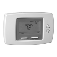
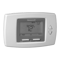
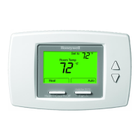
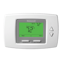
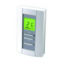
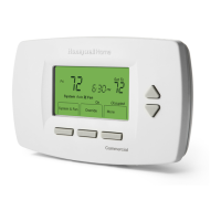
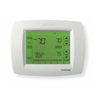
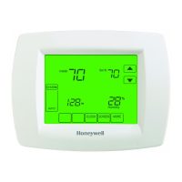
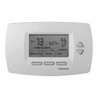
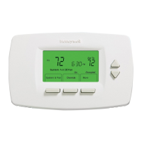
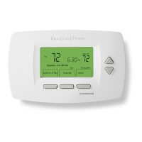
TB6575/TB8575 Digital Fan Coil
Thermostats
PRODUCT DESCRIPTION
The TB6575 and TB8575 are a family of Digital Fan Coil
thermostats for residential and commercial applications
such as hotels, condominiums, school classrooms, etc.
Three models are available for your application:
• TB6575A1000 – 2-pipe or 4-pipe with seasonal/
manual/automatic heat/cool changeover; 120/240
Vac.
• TB6575B1000 – 2-pipe only with seasonal or manual
heat/cool changeover; 120/240 Vac.
• TB8575A1000 – 2-pipe or 4-pipe with seasonal heat/
cool changeover; 24Vac.
All three models are suitable for multiple applications.
Changes in output wiring and external links between
wiring terminals allow you to configure the thermostat for
the appropriate application.
The applications that are available are:
• Heating or Cooling only
• Two pipes: Heat or Cool with Manual Changeover
• Two pipes: Heat or Cool with Seasonal Changeover
(requires optional pipe sensor)
• Two pipes: Heat or Cool with Auxiliary Heat and
Manual or Seasonal Changeover (requires optional
pipe sensor)
• Four pipes: Mixed Manual and Auto Changeover
• Four pipes: Manual Changeover
• Four pipes: Auto Changeover
The fan is controlled from the thermostat. The Low,
Medium, High, or Auto fan settings are easily made with
a press of a key.
Valves and auxiliary electric heaters can be controlled
using a relay or contactor controlled by the system
switch.
FEATURES
• Simple, intuitive user interface.
• Pre-installed lead wires for fast installation
(TB6575A and TB6575B models only)
• Backlight display permits easy viewing in any
light.
• Four buttons allow manual control of system
operation, fan speed, and temperature setpoint
adjustment.
• Digital display of ambient temperature, setpoint,
heating or cooling mode, fan status, and remote
setback
• Proportional plus Integral (P+I) control algorithm
for precision temperature regulation.
• Single Setpoint and Heat/Cool setpoint methods
for 4-pipe auto changeover.
• Adjustable maximum heating and minimum
cooling setpoint limits using range stops.
• EEPROM permanently retains user settings,
including setpoints, during power loss (no
batteries required).
• Selectable °C or °F display via Setup button on
thermostat.
• Displayable pipe sensor temperature readout to
aid in troubleshooting.
• Selectable to allow the fan motor to always begin
on high speed to ensure sufficient torque at
startup.
• Option to wire a remote indoor temperature
sensor.
• Freeze protect algorithm turns on heat when
needed.
• Economy Setback options via dry contact or
Activity Sensing
• Advanced fan control with VersaSpeed™ fan ramp
algorithm and Auto Fan Reset
Contents
Product Description ................................................... 1
Features .................................................................... 1
Specifications ............................................................ 2
Installation ................................................................. 3
Setup ......................................................................... 10
Operation ................................................................... 14
Troubleshooting ......................................................... 17