EasyManua.ls Logo

Honeywell ZONEPRO TB6980 User Manual

Honeywell ZONEPRO TB6980
6 pages
To Next Page IconTo Next Page
Page #1 background imageLoading...
Page #1 background image
TB6980/TB7980 62-0238 400-150-005-B 3/23/06 1/6
1. Introduction
The TB6980/TB7980 digital thermostats provide proportional plus
integral individual space temperature control in zoned commercial
HVAC systems such as hydronic and pressure dependent VAV with
or without reheat. There are four different models:
Depending on the model, the thermostat can have up to three out-
puts that can be used for the following applications:
Floating or Modulating damper/valve actuator control
Damper/valve actuator control with duct reheat and auxiliary
heat (B models only)
Hydronic systems (room control, perimeter heating and cool-
ing)
Accessories
R841 family of electromechanical relays
T7770A3002 remote room sensor
50014156-002 remote room sensor
32004800-001 bare thermistor
50014157-001 duct temperature sensor
2. Installation
2.1 Mounting Instructions
n Remove the thermostat from its base by unscrewing the cap-
tive screw and tilting the bottom of the thermostat up. The
screw cannot be completely removed.
o Pass the wires through the center hole of the base and secure
the base to the wall or onto an electrical box.
p Wire the thermostat. See section 2.2 for terminal designations
and section 3 for typical wiring diagrams.
q Reinstall the thermostat onto its base and secure with the cap-
tive screw.
2.2 Terminal Designations
The designations of the terminals vary according to the particular
model of thermostat. Refer to the following table for the description
of each terminal.
TB7980A (single output, modulating) TB6980A (single output, floating)
TB7980B (multiple output modulating) TB6980B (multiple output, floating)
Configuration and status display
Heating mode
Temperature display
Output power display
Temperature
adjustment
button
Cooling mode
Override button
TERMINAL DESCRIPTION
1
2
24 VAC
COM
Power supply
3
4
AN1
COM
Output 1
TB7980 models
3
4
OPEN
CLOSED
TB6980 models
5
6
T2/AN2
T2/COM
Output 2 (TB6980B and TB7980B models)
7
8
T3
T3
Output 3 (TB6980B and TB7980B models)
9
10
COM
SENSOR
External sensor input. (For applications requiring
an external sensor, see section 4.2.)
9
11
COM
C-Over
Mode Changeover input (N.O. contact). See sec-
tion 5.4.2.
9
12
COM
NSB
Night Setback activation input (N.O. contact).
See section 5.5.
Note: To configure the terminals, see section 4.
TB6980/TB7980
Installation and User Guide
ZonePRO Thermostat
Question and Answer IconNeed help?

Do you have a question about the Honeywell ZONEPRO TB6980 and is the answer not in the manual?

Honeywell ZONEPRO TB6980 Specifications

Power IconPower
power24 VAC
current consumption25 mA
Temperature Specifications IconTemperature Specifications
setpoint range10°C to 35°C (50°F to 95°F)
temperature display0°C to 60°C (32°F to 140°F)
temperature display resolution0.5°C (1°F)
mode hysteresis2°C (4°F)
automatic changeover deadband5°C (9°F)
nsb offsetProgrammable 1°C to 9°C (2°F to 18°F)
operating temperature32°F to 140°F (0°C to 60°C)
storage temperature-4°F to 122°F (-20°C to 50°C)
humidity limits0 to 95% R.H., non-condensing
Dimensions IconDimensions
dimensions69 x 118 x 27 mm (2.7 x 4.6 x 1.0 in.)

Summary

Introduction

Accessories

Lists available accessories for the TB6980/TB7980 thermostat system.

Installation

Mounting Instructions

Step-by-step guide on how to physically mount the thermostat base and unit.

Terminal Designations

Details the function of each terminal on the thermostat for wiring purposes.

Configuration

Configuration Menus

Explains the various configuration menu settings available for the thermostat.

Application Types

Describes different thermostat applications and their corresponding configuration settings.

Output 1

Details configuration for Output 1, used to control dampers in heating or cooling.

Output 2

Explains configuration for Output 2, which controls heating regardless of thermostat mode.

Output 3

Details configuration for Output 3, controlling heating or cooling based on settings.

Minimum and Maximum Setpoints

Defines the adjustable range for minimum and maximum temperature setpoints.

DIP Switches

Describes the function of DIP switches for temperature display and access mode.

Operation

Backlight

Information on how to activate and the duration of the thermostat's backlight.

Temperature Display and Setting

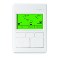
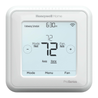
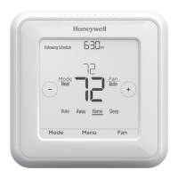
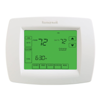
How to view and adjust the temperature setpoint on the thermostat display.

Output Display

Explains how to view the status of Output 1, 2, and 3 via the bar graph display.

Mode Changeover

Details how the thermostat switches between heating and cooling modes.

Night Setback

Describes the Night Setback (NSB) mode and how to override it.

Error Codes

Lists and explains potential error codes that may appear on the thermostat display.

Technical Specifications

WARRANTY

SERVICE

Related product manuals