Do you have a question about the Honeywell Z-Wave Series and is the answer not in the manual?
To protect yourself and your equipment, turn off power at the breaker box or switch controlling your heating/cooling system.
Change temperature on old thermostat. If no system turn-on within 5 minutes, power is off.
Grasp and gently pull faceplate. Some thermostats may have screws, buttons, or clasps.
Identify thick black wires with wire nuts or if thermostat is 120V or higher to avoid line voltage system incompatibility.
Capture image of wiring with terminal letters for reference when wiring the new thermostat.
Document wires present in terminals, excluding jumpers.
Mark connected wires and write down their corresponding colors.
Use a screwdriver to release wires, then label each wire matching the terminal letter.
Pull open UWP, insert wires through back, ensuring at least 1/4-inch is exposed.
Use UWP to mark and drill holes, then insert wall anchors flush with the wall.
Set R-switch based on wiring notes and insert wires into inner holes of UWP terminals.
Insert R and C wires into designated terminals for primary AC power. Remove wires by depressing terminal tabs.
Insert 3 AA batteries for primary or backup power, matching polarity to compartment marks.
Push tabs to insert wires into UWP terminals until firm. Gently tug to verify security.
Turn on power at the breaker box or switch controlling the heating/cooling system.
Return to thermostat, confirm 'START SETUP' screen, and touch START SETUP to begin.
Use navigation buttons to scroll through options and edit values by touching text or 'Edit'.
Continue until 'FINISH SETUP' is displayed, then touch 'Select' or text area.
Set daylight saving time, date, clock format, and time on subsequent screens.
Thermostat is now set up. Refer to page 8 for basic operation information.
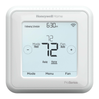
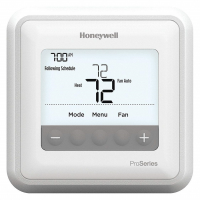
Displays current system status: Cool On, Heat On, Emergency Heat On, Recovery, Auto Changeover On.
Indicates time or occupancy-based temperature control is active.
Shows the target temperature setting for the system.
Displays current indoor temperature or percentage of indoor relative humidity.
Allows selection of system mode: Auto, Heat, Cool, Off, or Emergency Heat.
Access user options by touching Menu; access advanced options with a long press.
Indicates the current connection status of the thermostat within the Z-Wave network.
Shows device setup options, menu options, reminders, and schedule overrides.
Shows the current schedule period: Wake, Away, Home, or Sleep.
Allows selection of fan mode: Auto, On, or Circulate.
Certified for Z-Wave Plus, works with Z-Wave compliant controllers for programming and automation.
Fully programmable when not in Z-Wave network, with different settings for heating/cooling periods.
Shows ambient temperature, % relative humidity, and HVAC system status.
Automatically determines heating or cooling needs to reach desired temperature.
Notifies about HVAC system issues and reminds for filter changes.
Learns system cycle times to deliver desired temperature at the scheduled time.
Powered by 3x AA batteries or 24 VAC (C or common wire).
Configure schedule type: Non-Programmable, 1-Week, 5-2, 5-1-1, or 7-Day Programmable.
Select Fahrenheit or Celsius for temperature display.
Configure for wired outdoor sensor connection for balance point and Aux Heat lockout.
Select basic system type: Conventional Forced Air, Heat Pump, Radiant Heat, or None (Cool Only).
Select specific equipment: Gas Forced Air, Oil Forced Air, Electric Forced Air, Hot Water Fan Coil.
Select O/B terminal function for heat pumps: O/B in Cool or O/B in Heat.
Set number of Cool or Compressor stages (0, 1, or 2) for equipment control.
Set number of Heat or Aux/E stages (1, 2 for Heat; 0, 1 for Backup) for equipment control.
Select fan control: Equipment or Thermostat. Only for Electric Forced Air or Fan Coil.
Configure Auxiliary/Emergency heating control: Both Aux/E or Either Aux/E.
Define Emergency Heat type: Electric, Gas/Oil (or Fossil Forced Air).
Configure Fossil Fuel Kit control for Heat Pump systems.
Set automatic or manual control for heating and cooling system modes.
Set minimum degrees rise/fall for mode switching in auto-changeover.
Control higher cooling stage operation until setpoint is reached (for 2 cool stages).
Control higher heating stage operation until setpoint is reached (for 2+ heat stages).
Set Aux heat droop for heat pump systems: Comfort or degree increments.
Set timer for auxiliary heat activation after highest stage of previous heating equipment.
Set outdoor temperature to lockout heat pump and run Aux Heat only.
Set outdoor temperature to optimize energy bills by limiting expensive Aux Heat.
Set cooling cycle rate for stage 1 (cycles per hour at 50% load).
Set cooling cycle rate for stage 2 (cycles per hour at 50% load).
Set heating cycle rate for stage 1 (cycles per hour at 50% load).
Set heating cycle rate for stage 2 (cycles per hour at 50% load).
Set auxiliary heat cycle rate (cycles per hour at 50% load).
Set emergency heat cycle rate (cycles per hour at 50% load).
Set minimum off timer for compressor to prevent early restart after shutdown.
Set fan run time after cooling ends for increased efficiency.
Set fan run time after heating ends for increased efficiency.
Enable comfort setting to turn equipment on earlier for timely temperature match.
Set the lowest allowable temperature setpoint for cooling.
Set the highest allowable temperature setpoint for heating.
Configure screen lock: None, Partial, or Full.
Configure remote indoor sensor for temperature readings.
Select resistance type of wired indoor sensor (10k or 20k).
Choose temperature source: thermostat, wired, or average of both.
Set the number of air filters for system reminders.
Set reminders for changing air filters based on runtime or calendar.
Set reminders for humidifier pad, dehumidifier filter, and vent filter replacement.
Set reminders for UV bulb replacement for A-Coil and Air Treatment.
Adjust brightness of the inactive backlight (idle screen).
Select 12-hour or 24-hour clock format.
Enable or disable Daylight Saving Time setting.
Add or remove the thermostat from a Z-Wave network via the MENU/Z-WAVE SETUP.
Check thermostat inclusion status, node ID, and connection status within the Z-Wave network.
Change between battery mode or normal power mode when not included in Z-Wave network.
Indicates thermostat is included and successfully connected to a Z-Wave network.
Indicates the thermostat has been removed or excluded from the Z-Wave network.
Indicates Z-Wave signal loss or AC power loss, affecting radio operation and battery life.
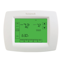
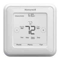
Press Mode button to cycle through Auto, Heat, Cool, Em Heat, or Off system modes.
Press Fan button to cycle through Auto, On, or Circulate fan modes.
Thermostat schedule is optional and appears if enabled in Installer Setup.
When in Z-Wave network, schedule follows controller; local schedule is OFF by default.
Only Home and Away periods appear on home screen when included in Z-Wave network.
Enable local schedule if controller lacks full thermostat class functions for differentiation.
Shows default Mon-Fri; Sat-Sun schedule when thermostat is included in Z-Wave network.
Ensure schedule is enabled via Installer Setup, ISU 120 for schedule type.
Functions as fully programmable when not operated by Z-Wave controller.
Shows default Mon-Fri; Sat-Sun schedule when thermostat is excluded from Z-Wave network.
Adjust temperature, hold until a specific time, then automatically returns to schedule.
Adjust temperature and hold permanently until manually changed.
Connect wires based on terminal labels or alternate configurations if labels do not match.
Instructions for connecting R, Rc, and RH wires based on R Slider Tab position.
Guidelines for connecting C or C1 wires, and handling multiple C wires.
Match labeled wires to thermostat terminals and insert.
Specific connection guidelines for heat pumps if labels do not match terminals.
Do NOT use W for heat pump applications; Auxiliary heat must wire to AUX or E.
Thermostat learns system time to reach programmed settings for comfort.
Replace immediately when low battery icon appears or annually. Alkaline batteries recommended.
Navigate Menu to Recovery and select ON or OFF to enable/disable Smart Response.
Navigate Menu to Clock, then SET TIME to adjust hours, minutes, and format.
Navigate Menu to DATE to set month, day, and year.
Lock the screen to prevent accidental changes while cleaning. Screen deactivates for 30 seconds.
Navigate Menu to TEMP SCALE to select FAHRENHEIT or CELSIUS.
Alerts for Humidity Sensor, Thermostat Temperature Sensor, Indoor/Outdoor Sensor errors.
Alerts for Heat Pump Needs Service, Air Filter, Humidifier Pad, Dehumidifier Filter, Ventilator Filter, UV Bulb replacement.
Alerts for Internal Memory Error and reminder to Set the Date and Time.
Indicates AC power loss; Z-Wave communication may turn off to preserve battery.
Alerts for Battery Low or Battery Critical status, requiring battery replacement.
Alerts for Z-Wave Not Configured or Z-Wave Radio Error, indicating setup or module issues.
Batteries are optional if thermostat was wired to 24 VAC power.
Low battery icon, backlight disable; critically low requires immediate replacement.
Check batteries, circuit breaker, furnace switch, and door closure.
Verify System Setup Option 220 settings for Cool mode.
Check setup options, temperature settings, circuit breaker, power switch, and furnace door.
Wait 5 minutes for the system to respond safely after compressor shutdown.
Check setup options and wiring (Aux heat runs in cooling, cool runs with call for heat).
Covers defects in workmanship/materials for one year. Excludes battery, removal/reinstallation costs.
Return to place of purchase or contact Resideo Customer Care for repair or replacement.
Disconnect power before beginning installation to prevent shock or damage.
Proper disposal instructions for thermostats containing mercury.
Visit website or call toll-free number for assistance with the product.
| Protocol | Z-Wave |
|---|---|
| Display | Backlit LCD |
| Power Source | Battery or Hardwired |
| Z-Wave Frequency | 908.42 MHz (US) |
| Humidity Sensor | No |
| Compatibility | Z-Wave certified hubs |
| Remote Access | Yes |
| Voice Control | Yes (with compatible hub) |
| Energy Saving Features | Yes |