10
Quick Installation Guide
System Setup options
Number Description Options (factory default in bold)
120 Scheduling Options
0 = NonProgrammable
1 = 1Week Programmable
2 = 52 Programmable
3 = 511 Programmable
4 = 7Day Programmable
Note: You can change default MOFR, SASU schedule here. To edit periods during days,
temperature setpoints, or to turn Schedule On/Off, touch MENU and go to SCHEDULE.
125
Temperature Indication
Scale
0 = Fahrenheit
1 = Celsius
130 Outdoor Temp
No, Wired
Note: An outdoor temperature is required to set the following ISUs: ISU 355 Balance point
(Compressor Lockout), ISU 356 Aux Heat Lockout. Use a wired outdoor sensor connected
to the “S” terminals on the UWP and set this ISU to Wired. (See “Wiring—heat pump” on
page 21.)
200 Heating System Type
1 = Conventional Forced Air Heat
2 = Heat Pump
3 = Radiant Heat (Boiler)
5 = None (Cool Only)
Note: This option selects the basic system type your thermostat will control.
205
Heating Equipment
Type
Conventional Forced Air Heat:
1 = Standard Efficiency Gas Forced Air
2 = High Efficiency Gas Forced Air
3 = Oil Forced Air
4 = Electric Forced Air
5 = Hot Water Fan Coil
Heat Pump:
7 = Air to Air Heat Pump
8 = Geothermal
Radiant Heat:
9 = Hot Water Radiant Heat
12 = Steam
Note: This option selects the equipment type your thermostat will control. Note: This feature is
NOT displayed if feature 200 is set to Cool Only.
218 Reversing Valve O/B
0 = O (O/B in Cool)
1 = B (O/B in Heat)
Note: This option is only displayed if the Heat Pump configured. Select whether reversing valve
O/B should energize in cool or in heat.
220
Cool Stages /
Compressor Stages
200=Conv / 200=HP
0, 1, 2
Note: Select how many Cool or Compressor stages of your equipment the thermostat will
control. Maximum of 2 Cool/Compressor Stages. Set value to 0 if you do not have Cool Stage/
Compressor Stage.
221
Heat Stages / Backup
Heat Stages Heat
Stages
Heat Stages: 1, 2
Backup Heat Stages: 0, 1
Note: Select how many Heat or Aux/E stages of your equipment the thermostat will control.
Maximum of 2 Heat Stages for conventional systems. Maximum of 1 Aux/E stage for systems
with more than 1 heating equipment type. Set value to 0 if you do not have Heat Stage/Backup
Heat Stage.
230 Fan Control
1 = Equipment
2 = Thermostat
Note: This ISU is only displayed if ISU 205 is set to Electric Forced Air or Fan Coil.
253 Aux/E Control
Both Aux/E, Either Aux/E
Note: Set “EITHER AUX/E” if you want to setup and control of Auxiliary and Emergency heating
separately . This ISU is only displayed if ISU 200 is set to Heat Pump AND if ISU 221 Aux/E
stages = 1.
255 Aux Heat Type
Electric, Gas/Oil (or Fossil Forced Air)
Note: This ISU is displayed only if ISU 200 is set to heat pump AND if ISU 221 Aux/E heat
stages = 1.
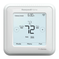
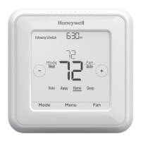
To access all system options in the table below, press and hold MENU for 5 seconds.
Touch
or
to scroll through the list.
 Loading...
