EasyManua.ls Logo

Honeywell TB3140B/U User Manual

Honeywell TB3140B/U
24 pages
To Next Page IconTo Next Page
Page #1 background imageLoading...
Page #1 background image
INSTALLATION INSTRUCTIONS
® U.S. Registered Trademark
Copyright © 2022 Honeywell Inc. • All Rights Reserved
31-00576-01
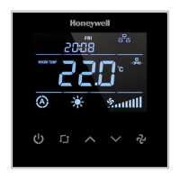
TB3 Series Communicating Thermostats
FOR 2-PIPE AND 4-PIPE FAN COIL UNITS
APPLICATION
TB3 Series Fan Coil Thermostats are used in individual
rooms or zones in buildings. It is designed for two and
four-pipe fan coil units. TB3 Series has one universal
input as an external sensor (NTC10k) or open/close
contact input, three relay fan outputs, two relay valve
outputs (TB3140), two analog valve outputs (TB3240),
and one EIA-485 (BACnet MS/TP). It controls the fan
coil unit depending on the internal room sensor or
external return sensor temperature.
The following NTC10K sensor and flange are
recommended: VF10-3B65NW and LF-MF
CAUTION
CAUTION
The authorized service must do assembly,
maintenance, diagnostic, and repair. The device's
power supply is 220 VAC (TB3140) and 24V
AC/DC (TB3240), and it has no internal fuse.
External protection with max C10A (TB3140)
and C5A (TB3240) circuit breakers are required
in all cases.
Disconnect the power supply before separating
the front plate.
INSTALLATION
Read these instructions carefully. Failure to follow
them could damage the product or cause a
hazardous condition.
Check the ratings in the instructions and the product
to ensure the product is suitable for your application.
The Installer must be a trained, experienced service
technician.
After installation is complete, check out product
operation as provided in these instructions.
All wiring must agree with applicable codes,
ordinances, and regulations, as specified in
installation wiring diagrams.
TB3 Series thermostat safety rules are in accordance
with the latest technological developments designed
and manufactured. Adhere to the safety precautions
to avoid injury and property damage.
CAUTION
CAUTION
Power off the supply at circuit breaker or fuse
before installation to avoid fire, shock, or death!

Questions and Answers:

Honeywell TB3140B/U Specifications

General IconGeneral
ProgrammableYes
Power SourceHardwired
Voltage24V
Weight0.5 lbs
Programmability7-day programmable
Stages1
CompatibilitySingle-stage heating and cooling systems

Summary

Installation Instructions

Safety Cautions

Important safety warnings regarding authorized service, power supply, and circuit breakers.

Product Specification

Mounting Location Guidelines

Installation Procedure

Step 1: Power Off

Instruction to switch off the power supply before starting the installation.

Step 5: Connect Wires

Instruction to connect wires according to the provided wiring diagram.

Step 9: Switch On Power

Powering on the thermostat to start the wall module and initiate operation.

Wiring Connection Diagrams

TB3140 Modulating Connection

Wiring diagrams for the TB3140 series for 2-pipe and 4-pipe fan coil units.

TB3240 Modulating Connection

Wiring diagrams for the TB3240 series for 2-pipe and 4-pipe fan coil units.

Wiring Note

Important note about circuit breaker protection and isolating NTC/dry contact cables.

User Interface and Key Functions

Mode Key Operations

Covers mode selection, time selection, schedule operation, and key lock.

Troubleshooting Common Issues

Cooling System Issues

Solutions for systems not cooling or continuously overcooling.

Heating System Issues

Solutions for systems not heating or continuously overheating.

Input and Password Issues

Addresses keypad unresponsiveness and forgotten passwords.

Password Setting Procedure

Initial Password Configuration

Explains the process of setting a 4-digit pin during first installation or reset.

Configuration Menu

Accessing Configuration Menu

How to enter the configuration menu by holding specific keys.

Universal Input Configuration

Universal Input Parameter P32 Definitions

Explains the different functions for P32, including external sensors and contacts.

Control Parameters

Fan and Valve Control Selection (P41)

How to select between valve-independent and valve-dependent fan control.

Hysteresis and Dead Zone (P40)

Explanation of hysteresis and dead zone settings for heating and cooling modes.

Restore Factory Settings

Factory Reset Procedure

Steps to perform a factory reset using key combinations.

Alarm Codes and Handling

Onboard Sensor Malfunction (AL01)

Details the alarm for onboard sensor errors and its impact on outputs.

External/Changeover Sensor Malfunctions (AL02, AL03)

Covers alarms for external or changeover sensor issues and how to disable them.

Firmware Update Procedure

Configuration Menu Parameters (P1-P14)

Setpoint Limits and Main Screen (P3-P5)

Configuration of setpoint limits and what is displayed on the main screen.

Configuration Menu Parameters (P15-P46)

Input and Changeover Settings (P30-P35)

Configuration for fan coil type, universal input, and changeover temperatures.

Control Logic Parameters (P38-P41)

Settings for auto mode, dead zone, hysteresis, and fan/valve control selection.

Configuration Menu Parameters (P47, P48)

BACnet Communication Parameters

MS/TP Port Configurations

Standard MS/TP configurations for MAC address, loop number, and baudrate.

TB3240 Series BACnet Registers

Analog Value Registers for TB3140x

Lists analog value registers for TB3140x, including Mode, Fan Speed, and Set Point.

Analog Value Registers (Continued)

Control Logic Analog Registers

Covers registers for Changeover Temperature, Mode Change Delay, Dead Zone, Hysteresis.

Analog Value Registers (TB3240x Focus)

TB3240 Analog Value Registers

TB3240 Analog Value Registers (Continued)

Control Logic and Fan Timing Registers (TB3240)

Registers for Mode Change Delay, Dead Zone, Hysteresis, Fan Stage Change Delay, Fan Off Delay.

Related product manuals