2 ST9400A, ST9400C Programmers Installation Guide 3
WIRING CONNECTIONS
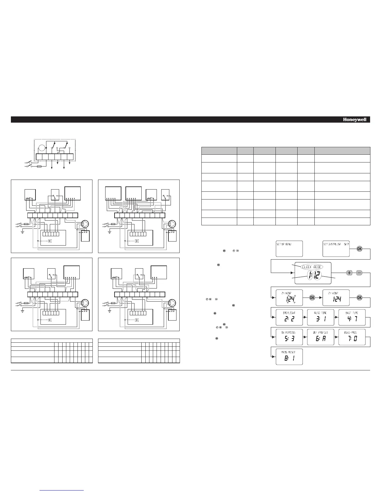
ST9400 Internal Wiring
Notes
1. The ST9400 is a Class II (double insulated) device. A parking
terminal is provided for earth wiring continuity, if required.
2. In the Sundial S-Plan, W-Plan, and Y-Plan wiring diagrams,
connections are shown to basic boilers only. For wiring connections
to Pump over-run boilers refer to Boiler manufacturers’ instructions
or to Honeywell for assistance.
3. It is recommended that gravity circulation hot water systems are
fitted with a suitable hot water control valve as shown in the Sundial
C-Plan system. For systems installed without this valve, ST9400
can be configured as a Mini-Programmer. This is done within the
Installer Mode (see page 3 for details). Refer to Honeywell for details
of suitable wiring schematics.
Sundial Plan Wiring Diagrams
Y-Plan
C-Plan
S-Plan
W-Plan
ADDITIONAL PRODUCT FEATURES
Installer Mode
The ST9400 has a special Installer Mode where some features can be adjusted to suit user lifestyle or preferences – these are called installer
Parameters, and are listed in the table below, along with a description of the options that are possible.
INSTALLER PARAMETER Parameter
Number
LoT™ Display
Description
Default Value Range of
Values
Description [LoT™ Display Description]
24hr or am/pm clock display 1 CLOCK MODE 12 12, 24 12 = am/pm display,
24 = 24hr display
[AM-PM]
[24 HOUR]
Configure backlight operation
(backlight consumes no
additional energy)
2 BACKLIGHT 2 0, 1, 2 0 = off,
1 = on if button pressed,
2 = on continuously
[NO B-LIGHT]
[B-L DELAY]
[B-LIGHT ON]
Enable/disable auto time
change
3 AUTO TIME 1 0, 1 0 = disabled,
1 = enabled
[NO CHANGE]
[TIME CHANGE]
* 1-day or 5/2-day or 7-day
operation
4 UNIT TYPE 7 1, 5, 7 1 = 1-day operation,
5 = 5/2-day operation,
7 = 7-day operation
[1-DAY]
[5-2 DAY]
[7-DAY]
Number of ON/OFFs per
day
5 ON PERIODS 2 (for ST9400A)
3 (for ST9400C)
2, 3 2 = 2 on/offs per day,
3 = 3 on/offs per day
[2 PER DAY]
[3 PER DAY]
Select default time
programme
6 DEF PROFILE A A, b, C A = standard,
b = at home,
C = economy
[PROFILE A]
[PROFILE B]
[PROFILE C]
Configure Mini-Programmer 7 MINI-PROG 0 0, 1 0 = standard programmer,
1 = Mini-Programmer
[NO M-PROG]
[M-PROG ON]
** Reset all parameters 8 PROG RESET 1 0, 1 0 = do not reset
1 = default parameters
[RESET OFF]
[RESET ON]
To Enter Installer Mode:
a.
Ensure the slider is in the RUN position, then press
and hold the and buttons together for 8
seconds. Ignore the ‘NOT VALID’ that is displayed
for a few seconds. The message ‘SET UP MENU’ will
show briefly, followed by ‘SET INSTALLER OK ?’
b. Press the button to take you into the Installer Mode
Parameter Menu.
c. Parameter 1 is now available to change. This is to
allow you to change the clock format from 12 hour
AM/PM to 24 hour. At every step, the LoT™ Display
will inform you what the parameter means and what
option you have selected. The parameter number is
shown on the display separated by a colon from the
parameter value.
d. You can change the parameter value by pressing the
or buttons. At this point the description in the
LoT™ Display will change and the parameter value
will flash. If you press the value will stop flashing
and will be saved for use.
e. Press to move to the next parameter available
for editing. The parameter number will change
accordingly.
f. Keep pressing to step around the list of parameters,
and use or buttons to change the parameter
value.
g. Any parameter changes that have been confirmed
with the button will be saved and used.
To Exit Installer Mode:
You can exit Installer Mode at any time by moving the
slider to the next position and then back again to RUN.
Note: Installer Mode will exit automatically after 10
minutes if the slider is not moved.
T6360/T4360
ROOM STAT
2 3 1
L641
CYL. STAT
2 1
C
V4073
MID-POSITION VALVE
BLUE
G/YELLOW
WHITE
GREY
ORANGE
3 AMPS
MAX
L
N
230V~
50...60Hz
BOILER
PUMP
E N L
L
N
E
ST9400
*NOTE 1
N
L 1 2 3 4
1 2 3 4 5 6 7 8 9 10
T6360/T4360
ROOM STAT
2 3 1
L641
CYL. STAT
2 1
C
V4043H
2 PORT ZONE VALVE
HEATING
BLUE
G/YELLOW
BROWN
ORANGE
GREY
V4043H
2 PORT ZONE VALVE
HOT WATER
BLUE
G/YELLOW
BROWN
ORANGE
GREY
3 AMPS
MAX
L
N
230V~
50...60Hz
BOILER
PUMP
E N L
L
N
E
ST9400
*NOTE 1
1 2 3 4 5 6 7 8 9 10
N
L 1 2 3 4
V4043H
2 PORT ZONE VALVE
BLUE
G/YELLOW
BROWN
WHITE
ORANGE
GREY
3 AMPS
MAX
L
N
230V~
50...60Hz
BOILER
PUMP
E N L
L
N
E
ST9400
*NOTE 1
L641
CYL. STAT
2 1
C
N
L 1 2 3 4
T6360/T4360
ROOM STAT
2 3 1
1 2 3 4 5 6 7 8 9 10
T6360/T4360
ROOM STAT
2 3 1
V4044
DIVERTING VALVE
G/YELLOW
BROWN
BLUE
L641
CYL. STAT
2 1
C
3 AMPS
MAX
L
N
230V~
50...60Hz
BOILER
PUMP
E N L
L
N
E
ST9400
*NOTE 1
N
L 1 2 3 4
1 2 3 4 5 6 7 8 9 10
* this parameter is NOT available on ST9400A, which is 1-day operation only.
** this parameter by default has a value of 1, unless you change any other parameter, when it will change to 0. Set it to 1 to reset all parameters back to defaults.
LoT™ Display
Parameter
Number
Parameter
Value
or
Y-Plan, S-Plan, and C-Plan Systems
10-WAY WIRING STRIP 1 2 3 4 5 6 7 8 9 10
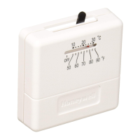
Honeywell T6360 ROOM-STAT 2 1 3
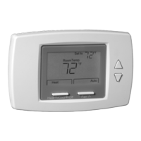
Honeywell ELECTRONIC THERMOSTAT
(BATTERY POWERED)
A B
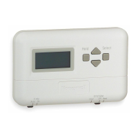
Honeywell WIRELESS THERMOSTAT
(RECEIVER UNIT) *
L N A B
* Wireless thermostat receiver unit MUST have permanent mains power from fused spur to operate correctly
Alternative Wiring Connections for other Honeywell Room Thermostats
W-Plan System
10-WAY WIRING STRIP 1 2 3 4 5 6 7 8 9 10
Honeywell T6360 ROOM-STAT 2 1 3
Honeywell ELECTRONIC THERMOSTAT
(BATTERY POWERED)
A B
Honeywell WIRELESS THERMOSTAT
(RECEIVER UNIT) *
L N A B
Clock
N L 1 2 3 4
3 AMPS MAX
HW OFF HW ON
CH OFF CH ON
N
L
OFF ON OFF ON
Wiring shown as a hot water priority system
 Loading...