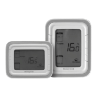
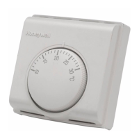
ROOM THERMOSTAT T6360
■ Installation
T
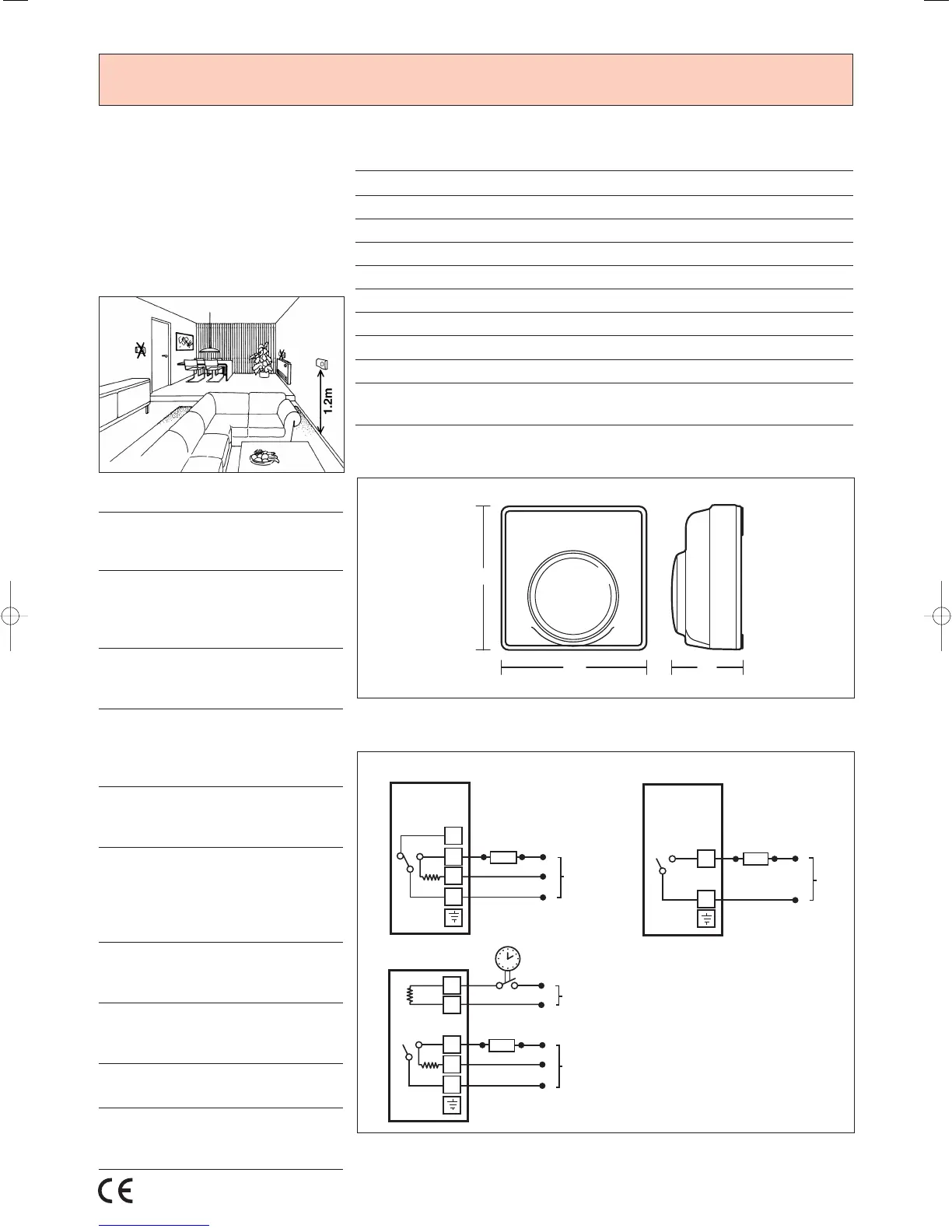
he T6360 thermostat must be
located where it is not subjected to
extraneous heat gains, direct sunlight
o
r draughts.
Fixing screws are supplied for either
surface or flush mounting box.
■ Ordering Specification
T6360B1028
Standard model complete with heat
anticipator and RFI suppressor
T4360B1015
High current rated version with SPST
switching and rated at 16A (resistive).
Without heat anticipator
T6360B1069
As standard model but with tamper
resistant cover and setting dial
T6360B1036
As standard model but with indicator
lamp on front cover which is lit on a
call for heat
T6360B1085
As standard model but with setting dial
marked 1 to 5
T4360E1018
Model with temperature setback heater
(fixed at 6°C) and SPST switching,
complete with anticipator heater and
RFI suppressor
F42007562-001
Accessory footprint for use when
replacing T6060 thermostats
F42006646-001
Bag assembly containing 20 range
stops and installation instructions
F42007110-001
Opaque tamperproof dial cover
TG510A1001
Lockable, clear plastic thermostat
cover. Backplate and spare keys inc
■ Specification
Voltage Rating : 230VAC, +/-10%, 50…60Hz
Switch Rating Terminal 3 : 10A resistive, 3A inductive
T
erminal 4 : 6A resistive, 2A inductive
Switch Type : Single pole, double throw (SPDT)
Temperature Setting Range : 10 to 30˚C
Temperature Control Accuracy : ± 0.5˚C at 3˚K/hour with anticipator
Storage Conditions : -20 to 55˚C
Humidity : 10 to 90% RH, non-condensing
Standards : CE marked
EC Directive : EN60730-1 (1995), EN55014-1
(1997), EN55014-2 (1996)
■ Dimensions (mm)
■ Wiring
Note:
1. Switching contacts are shown in the
normally open position – i.e. no heat
demand
2. Typical heating loads –
i) T4360B – electric heaters
ii) T6360/T4360E – motorised valves
 Loading...