62-0125—3
3
T7300F SERIES 2000 COMMERCIAL MICROELECTRONIC CONVENTIONAL
OR HEAT PUMP THERMOSTAT
Installer Setup numbers are listed in Table 2.
CAUTION
Possible equipment damage.
Fan must be running when system is operating
or equipment damage can result.
Heat pump and electric heat systems must be
configured in Installer Setup 2 to prevent equip-
ment damage caused by the system from running
without the fan.
IMPORTANT
Only configurable numbers are shown on the
device. Example: If thermostat does not have a
system key, Installer Setup Number 12 will not be
displayed. Review Table 2 factory-settings and
mark any desired changes in the Actual Setting
column. When Installer Setup is complete,
review the settings to confirm that they match
the system.
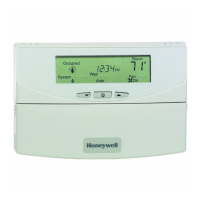
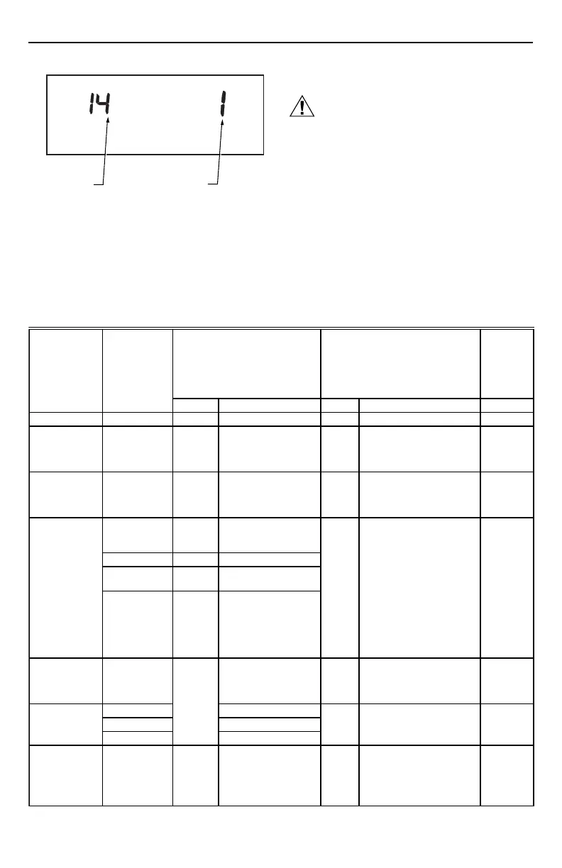
Fig. 4. Installer Setup number and setting display.
— To advance to the next Installer Setup number, press
the Unoccupied Temp key.
— To return to a previous Installer Setup number, press
the Heat/Cool Settings key.
— To change a setting, use the increase ▲ ▲ or ▼ ▼
decrease key.
— To exit the Installer Setup, press the Run Program
key. The Installer Setup is automatically exited if no
key presses are made for four minutes.
(Continued)
M10238B
INSTALLER SETUP
NUMBER DISPLAY
(COLUMN 2
OF TABLE 2)
FACTORY SETTING
OR OTHER CHOICE
DISPLAY (COLUMN 3
OR 5 OF TABLE 2)
Table 2. Thermostat Installer Setup Options.
Installer Setup
Number
(Press
Unoccupied
Temp Key
to
Factory Setting
Other Choices
(Press ∆ or ∇ key to change)
Actual
Setting
Select
change)
Display Description Display Description
Not used. 1 — — — — —
Fan operation
a
.2 0 Conventional applica-
tions where equipment
controls fan operation
in heat mode.
1 Electric heat applications
where thermostat controls
fan operation in heat
mode.
Output stages
of heating.
3 Depends
on
subbase.
Stages of heat. 0, 1, 2,
or 3
0—No heating.
1—One stage of heat.
2—Two stages of heat.
3—Three stages of heat.
Heating cycle
rate.
44Stage 1—4 cph. 3, 6, 8
or 9
3—3 cph used for hot
water systems or high
efficiency furnaces.
5 4 Stage 2—4 cph.
6
4 Stage 3—4 cph. 6—6 cph used for
conventional
systems.
74Emergency heat relay
is on continuously.
Highest stage of heat
cycles at 4 cph
(Q7300C,D,H [heat
pump models only]).
8—8 cph used for
conventional systems.
9—9 cph used for electric
heat systems.
Output stages
of cooling.
8 Depends
on
subbase.
Stages of cooling. 0, 1, 2
or 3
0—No cooling.
1—One stage of cool.
2—Two stages of cool.
3—Three stages of cool.
Cooling cycle 9 Stage 1—4 cph. 3 3—3 cph.
rate.
10 Stage 2—4 cph. 44 cph.
11 Stage 3—4 cph.
System setting
adjustment
(models with
System key).
12 Depends
on
model.
System selection. 0, 1 or
2
0—System setting key is
operational.
1—Auto setting is
disabled.
2—Auto only setting.
 Loading...