T775 SERIES 2000 ELECTRONIC STAND-ALONE CONTROLLERS
63-7147—3 18
Multi-Stage Boiler Control (No Reset) –
T775P
Application Description
The T775P is providing multistage boiler control based on the
boiler's discharge water temperature. The T775P uses the
fourth output relay to energize the primary pump.
Sensor Designation
This device application requires two sensors.
• Sensor A is sensing discharge water and is used to control
3 boiler stages.
• Sensor C is sensing the return water.
NOTE: Control can be to either sensor A or C.
Operation
In this example, as the heating load increases, additional
stages of heat will cycle ON as the boiler water temperature
decreases. The T775P will stage three boilers to provide
sufficient heating. (See Fig. 18.) The primary circulating pump
energizes whenever any stage is energized.
Programming Example
Program in Setup:
Press and hold the MENU button for 5 seconds to enter
Setup mode. Select the Outputs menu, and then select:
— # Stages = 3 (T775 assigns pump to Relay 4)
— Options
→ On Delay and Off Delay:
Seconds = 0 to 3,600 (default is 0)
— Options
→ WWSD = YES or NO
Temperature = 30 to 100° F (-1 to 38° C)
— STG4/Pump: (Relay 4 controls the pump output)
Enable = YES
Exercise = YES or NO
Prepurge = -300 to 300 seconds (default is 0)
Postpurge = 0 to 300 seconds (default is 0)
NOTES:
1. A positive Prepurge time causes the pump to
energize before the first stage energizes.
A negative time causes the pump to energize
after the first stage energizes.
2. The Postpurge time causes the pump to run for
the set number of seconds after the last stage
de-energizes.
Return to the Setup menu, and select Alarms:
— High Alarm = YES
— High Limit = 220° F (93° C)
NOTE: This model has Equal Runtime options, which can be
configured with the Lead Lag output option in Setup.
Stages 1-3: Control to the discharge water temperature
Program for:
— Setpoint = 200° F (93° C)
— Throttling Range = 18° F (-8° C)
—Sensor A
—Heat
IMPORTANT
After the desired value is selected, be sure to press
the # or $ or HOME button in order to save that
value in the controller’s memory.
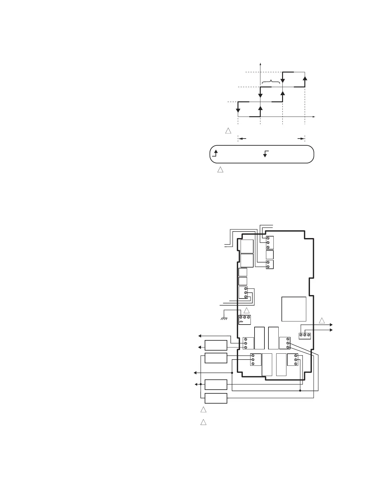
Refer to the staging diagram in Fig. 18 for individual stage
behavior.
Fig. 18. Boiler Control Staging Behavior (when the
effective setpoint = 200° F).
Wiring
All output relays should have a common power wiring source,
which may or may not be the same as the T775 power wiring.
Fig. 19. T775P Wiring - Multi-Stage Boiler Control
(No Reset).
M24867
THROTTLING RANGE (18°F)
STAGE 2 ON
STAGE 3 ON
STAGE 1 ON
-33%
STAGES
HYST.
0% 33% 67%
STAGE 1
STAGE 2
STAGE 3
1
1
DISCHARGE WATER TEMPERATURE
206°F 200°F 194°F 188°F
STAGE ENERGIZES STAGE DE-ENERGIZES
M24866
T
T
SENSOR A (DISCHARGE WATER)
C
NO
NC
C
NO
NC
C
NC
NO
C
NC
NO
T
T
RELAY
1
C
+
RELAY
4
RELAY
3
RELAY
2
T775P
PUMP
SENSOR C
(RETURN WATER)
L1
(HOT)
L2
C
NO
NC
DIGITAL OUTPUT
ALARM
NO
C
NC
L1
(HOT)
L2
120
COM
240
POWER WITH 24 VAC OR 120/240 VAC AT THE APPROPRIATE
TERMINAL BLOCK.
24 VAC POWER TERMINAL BLOCK.
1
1
2
120 VAC
2
BOILER #1
BOILER #2
BOILER #3
 Loading...