T775 SERIES 2000 ELECTRONIC STAND-ALONE CONTROLLERS
35 63-7147—3
T775L Replacement for S984 Step Controller
This replacement example illustrates how a T775L using a
T775S Expansion module is configured to replace a S984
Step Controller.
NOTE: This replacement section also applies to the S684
Step Controller.
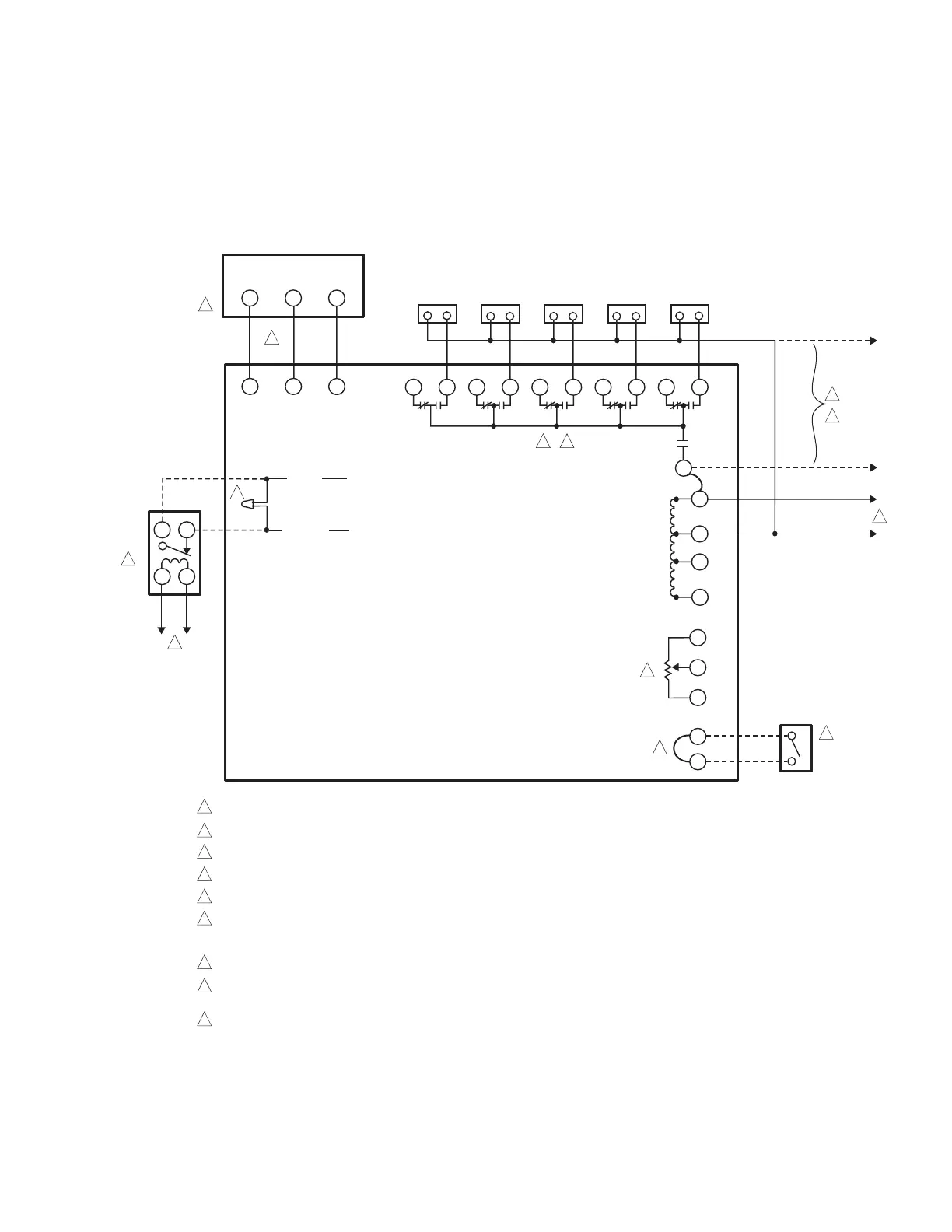
Fig. 38 illustrates the wiring connections for the S984 Step
Controller.
Fig. 39 and Table 5 on page 36 illustrate the wiring and
configuration of the T775L controller.
Fig. 38. S984 Wiring Connections (Pre-existing Control).
NOTE: The T775L Replacement for S984 Step Controller continues on the next page.
M28015
R
B
W
4
P
3
NO
NC
NO
NC
NO
NC
NO
NC
NO
NC
1
POWER SUPPLY. PROVIDE DISCONNECT MEANS AND OVERLOAD PROTECTION AS REQUIRED.
SWITCHES SHOWN WITH DEVICE ENERGIZED.
REFER TO SPECIFICATIONS FOR NUMBER OF SWITCHES.
AUXILIARY POTENTIOMETER ON S984J ONLY. TERMINAL LABELED “AUX.”
THIS HOOKUP IS FOR A COOLING SYSTEM. FOR A HEATING SYSTEM, REVERSE W AND B.
WHEN SHIPPED, LEADS ARE JOINED WITH A WIRE NUT. TO DELAY STAGES ON, REMOVE WIRE NUT FROM ORANGE AND WHITE
LEADS AND CONNECT TO DELAY TIMER. TO DELAY STAGES OFF, REMOVE WIRE NUT
FROM BLUE AND WHITE LEADS AND CONNECT TO DELAY TIMER.
REMOVE JUMPER AND CONNECT ON-OFF SWITCH HERE IF S984 MUST RETURN TO START PPOSITION DURING OFF CYCLE.
CLIP OUT JUMPER (TERMINAL 6 TO L1) AND CONNECT SEPARATE POWER SOURCE HERE IF SEPARATION OF SWITCHING STAGES
AND CONTROL OPERATION IS DESIRED.
NOT PART OF STEP CONTROLLER.
3
2
4
5
7
6
8
9
STAGE 1 STAGE 2 STAGE 3 STAGE 4 STAGE 5
L2
L1
R
B
W
R
B
W
N
6
1
3
2
4
ON-OFF
SWITCH
S400A
DELAY
TIMER
S984 STEP CONTROLLER
SERIES 90
CONTROLLER
WHITE
ORANGE
L1 (HOT)
L1 (HOT)
L2
L2
1
1
8
1
5
9
7
4
9
2 3
9
6
L1 (HOT) L2
1R1
 Loading...