T775 SERIES 2000 ELECTRONIC STAND-ALONE CONTROLLERS
63-7147—3 36
T775L Replacement for S984 Step Controller
(continued)
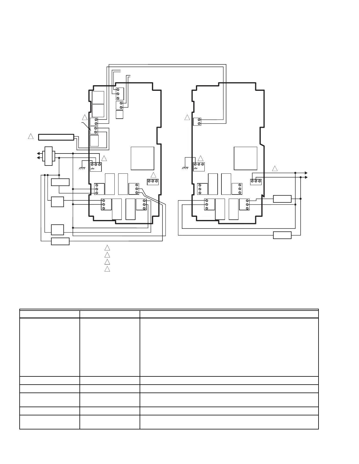
NOTE: Fig. 39 is for wiring purposes only. A thorough review
of the existing S984 application is required in order to
determine the capability of the T775 controller
replacement.
Fig. 39. T775L Wiring Connections for Replacing a S984 Step Controller.
In this replacement application, the T775L provides the following, as described in Table 5:
Table 5. T775L Replacement for S684 or S984.
Component/Function S684 or S984 T775L Replacement
Sensor Series 60, Series 90,
T915, T991, T921,
W902, etc. controller
Sensor A - Standard 1097 Ohm temperature sensor.
Sensor B - Standard 1097 Ohm temperature sensor; (required only if reset
control is used; i.e. a T991B or W902A controller was used.)
See “Temperature Sensors” on page 3.
NOTE: If you are implementing two-sensor reset control, Sensor A must
always be the controlled temperature and Sensor B must always
be the controlling temperature. For example, in a reset control
based on outside temperature, Sensor A must be the inside sensor
and Sensor B must be the outside sensor.
Delay Timer S400A Use the On Delay and Off Delay programmable parameters of the T775L.
Throttling Range n/a Set the programmable Throttling Range parameter to match the application.
Reset T991B or W902A
(if used)
Reset programming in the T775L provides the reset curve.
Loads 1 - 5 n/a Program the 5 relays into a single loop.
Auxiliary Pot. S964J only The T775L Controller with two T775S Expansion modules allows for up to
12 relay outputs.
M28018
T775 BUS TERMINALS PROVIDE WIRING CONNECTIONS TO/FROM T775L AND T775S.
SETUP THE CONTROL (T6031 OR T765) SO THAT IT CLOSES ON A TEMPERATURE FALL.
POWER WITH 24 VAC OR 120/240 VAC AT THE APPROPRIATE TERMINAL BLOCK.
24 VAC POWER TERMINAL BLOCK.
1
2
T775L T775S
C
NO
NC
C
NO
NC
C
NC
NO
C
NC
NO
T
T
+
–
L1
(HOT)
L2
24 VAC
COM
NO
COM
NO
COM
NO
COM
NO
HEAT
2
HEAT
1
C
NO
NC
C
NO
NC
C
NC
NO
C
NC
NO
+
–
3
120 VAC
COOL 3
COM
NO
1
SENSOR A (C7100D1001)
1
C
+
C
+
RELAY
3
RELAY
7
RELAY
6
RELAY
5
RELAY
2
RELAY
1
RELAY
4
RELAY
8
120
COM
240
120
COM
240
T
T
COOL 4
COM
NO
SENSOR B (SPACE OR OUTDOOR TEMPERATURE)
–
+
DIGITAL INPUT
(HEAT/COOL CHANGEOVER)
T6031 OR T675A
2
3
COOL 1
COOL 2
4
4
3
4

 Loading...