T775 SERIES 2000 ELECTRONIC STAND-ALONE CONTROLLERS
63-7147—3 26
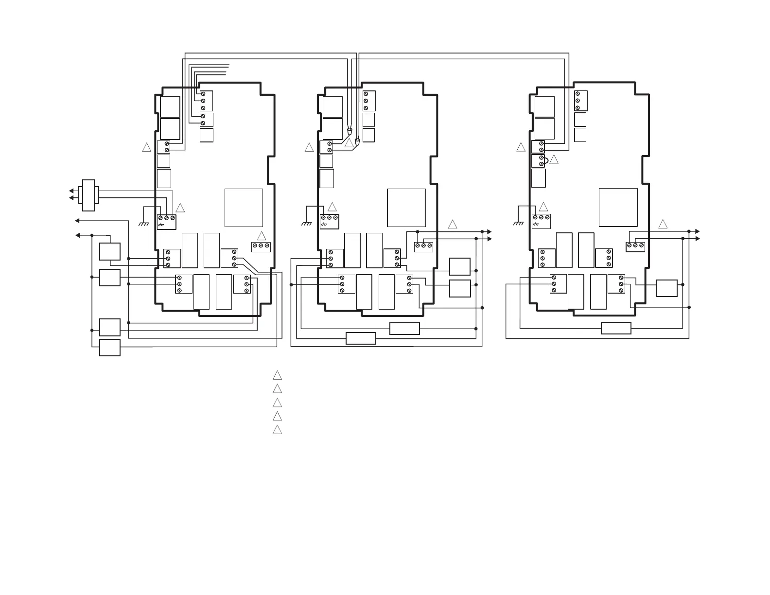
4 Stage Heat and 6 Stage Cool (continued)
Fig. 31. T775L Wiring - 4 Stage Heat and 6 Stage Cool using 2 Loops.
T775L FIRST
T775S
C
NO
NC
C
NO
NC
C
NC
NO
C
NC
NO
T
T
+
–
L1
(HOT)
L2
COM
NO
HEAT
4
COM
NO
COM
NO
COM
NO
HEAT
3
HEAT
2
HEAT
1
C
NO
NC
C
NO
NC
C
NC
NO
C
NC
NO
T
T
+
–
COOL 3
COOL
1
COOL
2
COM
NO
COM
NO
COM
NO
NO
COOL 4
1
SENSOR A
1
SECOND
T775S
C
NO
NC
C
NO
NC
C
NC
NO
C
NC
NO
T
T
+
–
+
–
COOL 5
COOL
6
COM
NO
COM
NO
1
3
2
T775 BUS TERMINALS PROVIDE WIRING CONNECTIONS TO/FROM T775L AND T775S.
USE PIGTAIL CONNECTIONS TO WIRE THE T775 BUS TERMINALS ON THE FIRST T775S
SECOND T775S MUST HAVE A JUMPER INSTALLED AS SHOWN AT THE JUMPER TERMINAL.
POWER WITH 24 VAC OR 120/240 VAC AT THE APPROPRIATE TERMINAL BLOCK.
24 VAC POWER TERMINAL BLOCK.
1
2
3
M27239
C
+
C
+
C
+
RELAY
3
RELAY
7
RELAY
6
RELAY
5
RELAY
2
RELAY
1
RELAY
4
RELAY
8
RELAY
11
RELAY
10
RELAY
9
RELAY
12
120
COM
240
120
COM
240
120
COM
240
SENSOR B
T
T
L1
(HOT)
L2
24 VAC
4
120 VAC
4
120 VAC
4
5
55
4
5
 Loading...