T775L SERIES 2000 ELECTRONIC STAND-ALONE STAGING CONTROLLER
62-0257—11 18
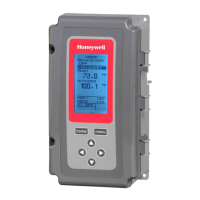
Fig. 38. Setup - Outputs - Loop 1 - Number of Relays.
1.3.4.1. Number of RELAYS
1. From the Loop 1 menu, use the and buttons to
highlight # RELAYS.
2. Press the button to display the number of relays.
3. Use the and buttons to select the number of
relays depending on setup. (SeeSee “1.3.1. Num-
ber of RELAYS” on page 14.)
4. Press the button to accept the value and display
the Loop 1 menu.
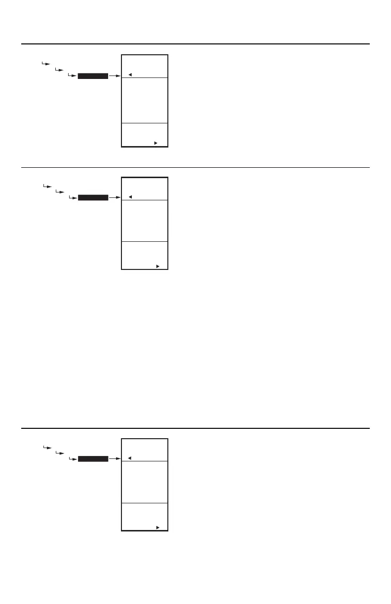
Fig. 39. Setup - Outputs - Loop 1 - Integral.
1.3.4.2. INTEGRAL
1. From the Loop 1 menu, use the and buttons to
highlight INTEGRAL.
2. Press the button to display the integral value.
3. Use the and buttons to change the integral
time from 0 to 3,600 seconds in increments of 10
seconds.
Default: 400 seconds
Range: 0 to 3,600 seconds
4. Press the button to accept the value and display
the Loop 1 menu.
NOTES:
1. The Integral time is factory set for 400 seconds. This
is a good middle range and should satisfy many
applications. The integral time can be increased for
applications where sensed response is slow, and can
be decreased for applications where sensed
response is fast (e.g. discharge air control).
2. As a starting point, an optimal integral time for
discharge air typically ranges from 12 to 200
seconds. An optimal integral time for room control
typically ranges from 60 to 2,500 seconds. The
purpose of integral action is to reduce or eliminate
the offset from setpoint during steady state control
that is often seen in proportional only control.
3. Keep in mind that control is most sensitive to
throttling range. Adjust the throttling range first
before any adjustment to integral time. Adjust
throttling range to be as wide as possible to start
since this will provide the most stable control.
Remember that the integral will eliminate the steady
state error so you do not need to have a small
throttling range to have accurate control. (Integral
action allows for controlling to a setpoint even with a
wide throttling range).
Fig. 40. Setup - Outputs - Loop 1 - Derivative.
1.3.4.3. DERIVATIVE
The Derivative default value is factory set to zero (no
derivative control). It is strongly recommended that the
derivative remain at zero (0) unless you have a very good
reason to adjust it. Derivative control is not needed in the
vast majority of HVAC applications.
1. From the Loop 1 menu, use the and buttons to
highlight DERIVATIVE, then press the button to
display the derivative seconds.
2. Use the and buttons to increase/decrease the
value.
Default: 0 (zero)
Range: 0 to 3,600 seconds
3. Press the button to accept the value and display
the Loop 1 menu.
ENTER
NUMBER OF
RELAYS FOR
LOOP 1
SETUP
OUTPUTS
LOOP 1
# RELAYS
3
SETUP
OUTPUTS
LOOP 1
# RELAYS
M24446
SETUP
OUTPUTS
LOOP 1
INTEGRAL
SETUP
OUTPUTS
LOOP 1
INTEGRAL
400
SEC
ENTER
INTEGRAL
TIME
FOR
LOOP 1
M24447
SETUP
OUTPUTS
LOOP 1
DERIVATIV
SETUP
OUTPUTS
LOOP 1
DERIVATIV
0
SEC
ENTER
DERIVATIVE
TIME
FOR
LOOP 1
M24448
 Loading...