69-0889 2
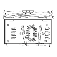
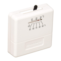
Loosen the terminal screws and slip each wire beneath
its matching terminal. See Fig. 2 for wiring insertion tech-
niques. Tighten terminals securely.
Plug the hole in the wall with insulation to help prevent
drafts from adversely affecting thermostat operation.
Fig. 2—Proper wiring technique.
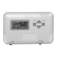
Fig. 3—2-wire heat-only application (jumper
intact).
R
Rc
W Y G
B D
A C
2-WIRE HEAT-ONLY (JUMPER INTACT)
M1709B
L1
(HOT)
L2
POWER SUPPLY. PROVIDE DISCONNECT MEANS AND
OVERLOAD PROTECTION AS REQUIRED.
1
1
HEATING
RELAY OR
VALVE COIL
JUMPER
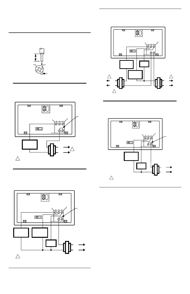
Fig. 4—4-wire heat/cool application (jumper
intact).
Fig. 5—5-wire heat/cool application (jumper
removed).
R
Rc
W Y G
B D
A C
4-WIRE HEAT/COOL (JUMPER INTACT)
L1
(HOT)
L2
POWER SUPPLY. PROVIDE DISCONNECT MEANS AND
OVERLOAD PROTECTION AS REQUIRED.
1
JUMPER
HEATING
RELAY OR
VALVE COIL
M1710B
COOLING
CONTACTOR
COIL
FAN
RELAY
R
Rc
W Y G
B D
A C
5-WIRE HEAT/COOL (JUMPER REMOVED)
L1
(HOT)
L2
POWER SUPPLY. PROVIDE DISCONNECT MEANS AND
OVERLOAD PROTECTION AS REQUIRED.
1
M1711B
L1
(HOT)
L2
COOLING
CONTACTOR
COIL
FAN
RELAY
HEATING
RELAY OR
VALVE COIL
1 1
Fig. 6—3-wire cool-only application (jumper
intact).
R
Rc
W Y G
B D
A C
3-WIRE COOL-ONLY (JUMPER INTACT)
L1
(HOT)
L2
POWER SUPPLY. PROVIDE DISCONNECT MEANS AND
OVERLOAD PROTECTION AS REQUIRED.
1
JUMPER
M848A
COOLING
CONTACTOR
COIL
FAN
RELAY
ADJUST FAN OPERATION SWITCH, AS
REQUIRED
The thermostat fan operation switch, labeled FUEL
SWITCH (see Fig. 7), is factory-set in the F position. This
is the correct setting for most systems. If this system is an
electric heat system, set the switch to E. The E setting
allows the fan to turn on immediately with the heating or
cooling in a system where the G terminal is connected.
ADJUST BURNER ON-TIME, AS REQUIRED
The thermostat burner on-time is factory-set for a warm
air, gas or oil heating system. When installing it on another
type of system, adjust the burner on-time accordingly by
setting screws A and B on the back of the thermostat, using
the heating system table in Fig. 7 as a guide. To minimize
room temperature swings, optimize the on-time according
to the type of system (see Table 2). Adjusting the screw
“out one turn” means turning the screw approximately
360°, or about one complete turn.
M3825
INSERT
STRAIGHT
UNDER
SCREW HEAD
5/16 in.
(8 mm)
STRIP
END OF WIRE
VISIBLE HERE
PROPER WIRING TECHNIQUE

 Loading...