T87F ZONE THERMOSTAT AND 137421N,P WALLPLATES; T87F ZONE THERMOSTAT AND Q539A,B SUBBASES
69-0579-4 2
Selecting Location
• Install the thermostat about 5 ft (1.5 meters) above the
floor in an area with good air circulation at average
temperature.
• Do not install the thermostat where it can be affected
by:
— drafts or dead spots behind doors and in corners.
— hot or cold air from ducts.
— radiant heat from sun or appliances.
— concealed pipes and chimneys.
— unheated (uncooled) areas such as an outside
wall behind the thermostat.
• Handle this thermostat carefully; it is a precision
instrument that was carefully calibrated at the factory.
CAUTION
Electrical Shock Hazard
Can cause personal injury or equipment
damage.
Disconnect power supply before installation.
Mounting and Wiring
IMPORTANT
To prevent interference with thermostat linkage,
keep wire length to a minimum and run wires as
close as possible to the subbase.
All wiring must comply with local codes and ordinances.
T87F Zone Thermostat and wallplate or subbase are
used in zoned conventional single-stage heating or
heating-cooling systems.
137421 Wallplate or Q539 Subbase
REPLACEMENT APPLICATION
1. Remove old equipment. Dispose of properly. See
Mercury Notice.
2. Check the existing wallplate or subbase wires for
cracked or frayed insulation.
3. Replace any wires in poor condition.
4. If the wires are plastered into the wall, make a hole
next to the wires so they can be pushed back into
the wall later.
5. Continue with step 3 for New Installation.
NEW INSTALLATIONS
1. Run low voltage thermostat cable (if necessary) to
the thermostat location.
2. Pull about 3 in. (76 mm) of cable through a hole in
the wall.
3. Connect wires to the terminals inside the wallplate
or subbase. See Fig. 1 and 2 or zone control panel
installation instructions for wiring diagrams of typi-
cal zone systems.
4. Push excess wire back through the hole and plug
any opening with insulation to prevent drafts that
can affect thermostat performance.
5. Loosely fasten the thermostat wallplate or subbase
to the wall with a screw through the left mounting
hole. See Fig. 3.
6. Adjust the wallplate or subbase so it is approxi-
mately level and start the second screw through
the right mounting slot. Do not tighten.
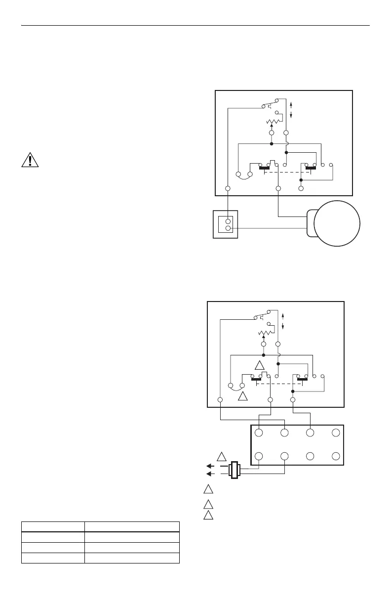
Fig. 1. Wiring single ARD (power open) to thermostat.
Fig. 2. Wiring T87F Thermostat and Q539B Subbase
or 137421 Wallplate in independent zone.
137421 Wiring Cross Reference
Old Terminal New Terminal
4W
5R
6Y
J
HEAT COOL HEAT COOL
Y/6
M14842
W/4
Y
TEMPERATUE RISE
W
ADJUSTABLE
HEAT
ANTICIPATOR
T87F3715/Q539B1039
T87F3707/Q539B1021
T140 TRANSFORMER
ARD CONFIGURED
WITH POWER OPEN
R/5
J
R
C
TEMPERATUE FALL
4
5 6 Z
1 2 3
X
DAMPER
ACTUATOR
L2
L1
POWER SUPPLY. PROVIDE DISCONNECT MEANS AND OVERLOAD
PROTECTION AS REQUIRED.
NO SYSTEM SWITCHING ON 137421 WALLPLATE.
FOR CORRECT SYSTEM OPERATION, DO NOT DISCONNECT FACTORY-
INSTALLED J-J JUMPER ON Q539B.
M19059
(HOT)
(COM) (HOT)
1
1
2
2
3
3
J
HEAT COOL HEAT COOL
Y/6W/4
Y
TEMPERATUE RISE
W
ADJUSTABLE
HEAT
ANTICIPATOR
T87F3715/Q539B1039
T87F3707/Q539B1021
R/5
J
TEMPERATUE FALL
 Loading...