EasyManua.ls Logo

Honeywell TA3840 - User Manual

Honeywell TA3840
30 pages
Print Icon
To Next Page IconTo Next Page
Loading...
Data Processing Racks
TA3840
Maintenance Manual
SAS au Capital de 2 158 244
- 444 871 933 R.C.S. Bourges - APE : 2651B
Headquarter : 9, rue Isaac Newton - 18000 Bourges - France

Other manuals for Honeywell TA3840

Question and Answer IconNeed help?

Do you have a question about the Honeywell TA3840 and is the answer not in the manual?

Summary

Introduction

Safety and Related Documents

Covers safety precautions and references to other relevant manuals.

System Overview and Warnings

Warnings and Regulations

Details general warnings, compliance with directives, and regulation marking.

System Description

System Components

Describes the TA3840 system, its units, and electronic boards.

System Maintenance

Maintenance Operations

Covers accessing maintenance mode, menu functions, RAW menu, and historic faults.

Software Updating

Provides information on updating the system's software using EPROMs.

Troubleshooting Guide

Troubleshooting Procedures

Outlines initial checks and unit-specific fault diagnosis and remedies.

Remedial Maintenance

Spare Parts and Repair Overview

Lists recommended spare parts and provides an overview of repair procedures.

Spare Parts List

Component Ordering Codes

Provides ordering codes for TA3840C, TA3840S, and TA3840R unit components.

Information and Support

Claims and Returns

Details the processes for submitting claim reports and returning equipment for repair.

Overview

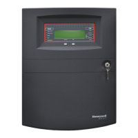
The Honeywell TA3840 Data Processing Racks are integral components of the TA3840 or EMx40 system, designed for monitoring liquid cargo parameters on tankers. This system tracks essential measurements such as level, temperature, and pressure, along with other associated data from installed transmitters. The TA3840C communication unit, TA3840R remote display unit, and TA3840S safety unit form the core of this system. Additionally, the TA3840C A/D Analog data collection unit is part of the TA840 System.

Function Description:

The TA3840 system is primarily used for processing liquid cargo data on tankers. It consists of several racks:

  • TA3840C Communication Unit: This unit handles communication within the system and with external applications. It includes a power supply and communication board, a Control Processing Unit (CPU) board, an LCD display board, and optional 4-20 mA analog input boards (48 channels each) or multifunction boards.
  • TA3840C A/D Data Collection Unit: This unit is responsible for collecting analog data. It contains the power supply and communication board, and the 4-20 mA analog input boards or multifunction boards. The front panel of this unit is blind.
  • TA3840S Safety Unit: This unit is designed for safety functions within the system. It includes a power supply board, a location for an optional Control Processing Unit board, and radar transmitter supply boards (up to 7).
  • TA3840R Remote Display Unit: This unit provides a remote display interface for the system. It consists of a communication board and an LCD display board.

The racks TA3840C, TA3840C A/D, and TA3840S are typically installed in a 19-inch cabinet. The TA3840R panel can be installed in a wall-mounting box or flush-mounted in a console.

Important Technical Specifications:

The equipment is designed and manufactured in accordance with local safety regulations and European directives, including:

  • 89/336/EEC and 2004/108/EC: "Electromagnetic compatibility"
  • ATEX 94/9/EC: "Equipment and protective systems intended for use in potentially explosive atmospheres"
  • 96/98/EC: "Marine equipment"

The TA3840S rack's manufacturer and specifications plate, located on the rear face, provides details such as:

  • Manufacturer's name and address: Honeywell Marine, 9, rue Isaac Newton, ZA Port Sec Nord, 18000 Bourges, France.
  • Serial number: TYPE: TA3840S, S/N: [Serial Number], DATE: [Date].
  • ATEX Marking: II (1) G [Ex ia Ga] IIB Uo, Io, Po, Co and Lo (refer to examination certificate LCIE 04 ATEX 6135 X, IECEX LCI 12... pending). This indicates compliance with directive 94/9/EEC for equipment in class IIB. An alternative marking for class IIC is also present: II (1) G [Ex ia Ga] IIC Uo, Io, Po, Co and Lo (refer to examination certificate LCIE 04 ATEX 6135 X, IECEX LCI 12.0000x).
  • CE Marking: CE 0081 (for IIB) and CE0001 (for IIC).

Usage Features:

The system is intended for professional use and requires installation, operation, and maintenance by competent and qualified staff. The maintenance menu, accessed via the UTILITIES menu (MODE and MNT) and a password ("6854" or system-defined code), offers several functions:

  • UP/DOWN: Navigate through pages or lines.
  • RAW: Display raw values from transmitters.
  • HIST: View the history of system faults.
  • RTN: Return to the main menu or maintenance menu.
  • OFST: Modify the offset for displayed transmitters (groups 1 and 2 only).
  • ZLN: Modify the zero line for displayed transmitters.
  • ACK: Acknowledge alarms triggered during maintenance mode.

The RAW menu allows displaying raw values measured by each transmitter and modifying the measure reference from the bottom (zero line) or top (OFFSET) for radar transmitters. Various types of displays are available for different transmitters, including radar transmitters, analog transmitters associated with radar, and 4-20 mA analog transmitters. Users can enter values within suggested limits for offset and zero line modifications.

The HISTORIC menu saves the last 100 system fault events, including date, time, slave number, error code, and a description of the failure. Error codes range from 001 to 116, covering issues such as radar transmitter communication, invalid measurements (distance, temperature, analog), and monitoring communication faults.

Maintenance Features:

Maintenance interventions should only be performed with electrical power off. Equipment must be wired by a qualified electrician, ensuring mains connection, grounding, circuit breaker, and protection conform to current standards.

Safety Precautions:

  • Do not expose equipment to water projections.
  • Switch off power before disconnecting or removing racks.
  • Never introduce metal parts into air vents.
  • Ensure racks are well-ventilated and air vents are not covered.
  • Keep racks distant from heat sources.
  • Refer to the MI5008E installation manual for jumper locations if removed during board interventions.

Troubleshooting Guide:

Preliminary checks for system failures include:

  • Checking system electrical protection.
  • Verifying 24 Vdc power supply on the TA3840C terminal block.
  • Checking main supply on the TA3840S terminal block.
  • Ensuring cable connections are secure and in good condition.
  • The voltage next to the terminal block must match the mains system voltage. If a blown fuse is identified, the cause of the short circuit must be investigated.

A detailed troubleshooting table is provided for various observations, likely causes, and remedies for TA3840S Safety unit, TA3840C Communication unit, TA3840C A/D Communication unit, and TA3840R Remote display unit. Common issues include power supply problems, blown fuses, faulty boards (power supply, CPU, LCD display, radar transmitter supply, analog input, multifunction), ribbon cable connection issues, and communication faults. Remedies often involve replacing fuses, boards, or checking/securing connections.

Software Updating:

Honeywell Marine provides sets of two EPROMs ("EVEN" and "ODD") for software updates. These EPROMs must be inserted into the relevant electronic boards, taking care not to damage the pins. Specific software versions are:

  • TA3840C soft: SOFT 1024.
  • TA3840R soft: SOFT 1025.
  • TA3840S soft (CPU board optional): SOFT 1004 (standard CPU board, ref. M11555) or SOFT 1007 (CPU board protocol P-Net, ref. M12922).

Repair Procedures:

Detailed instructions are provided for removing and installing various electronic boards and replacing fuses:

  • TA3840C Power supply and communication board: Unscrew 4 screws, pull handle to extract. Fuse F1 is a 1 A temporized fuse.
  • TA3840C 4-20 mA analog inputs or multifunction board: Raise 2 extractor levers to extract. Ensure correct slot for re-installation.
  • TA3840C LCD display board and CPU board: Disconnect ribbon cables and 10-pin/2-pin connectors. Remove 4 nuts for LCD display board. Unsolder and re-solder 2 wires for LCD display board, observing color (orange (+) top, black (-) bottom).
  • TA3840C Front face: Remove 2 upper screws, tilt panel, disconnect connectors, remove panel. Reinstall in reverse order.
  • TA3840S Power supply board: Unscrew 4 screws, pull handle to extract.
  • TA3840S Radar transmitter supply board: Push lower lock, raise and pull upper extractor lever to extract. Fuses F1 (200 mA D1TD), F2 (200 mA D1TD), F3 (250 mA temporized), and F4 (250 mA temporized) are specified for Category IIB and IIC.
  • TA3840R LCD display board and Communication board: Remove front face. Disconnect connectors and unsolder wires for LCD display board.

Two standard fuse kits are supplied:

  • Fuses kit for TA3840C and TA3840S class IIB: code 34766.
  • Fuses kit for TA3840C and TA3840S class IIC: code 34767. A comprehensive spare parts list is provided with ordering codes for TA3840C, TA3840S, and TA3840R components, including various boards (power supply, CPU, analog input, multifunction, communication, LCD display), EMC filters, interconnection boards, and front faces.

Claim Report and Return for Repair:

A claim report (Annex A) must be filled out and faxed to Honeywell Marine for any service requests or spare part needs. This report is required before any intervention. A return for repair form (Annex B) must accompany defective equipment sent back to Honeywell Marine, providing details to identify the defect and facilitate repair. The form includes sections for instrument description, problem description, application details, and a declaration of equipment cleanliness and decontamination. Equipment should not be sent before receiving an RMA number.

Honeywell TA3840 Specifications

General IconGeneral
BrandHoneywell
ModelTA3840
CategoryIndustrial Equipment
LanguageEnglish

Related product manuals