Do you have a question about the Honeywell Enraf 1010 CB and is the answer not in the manual?
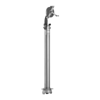
Describes the setup procedures for the Model 1010 loading system and its intended audience.
Defines key terms and conventions used in the manual for clarity.
Details the methods for accessing and exiting the instrument's programming interface.
Explains how to move through menus and select options within the programming mode.
Outlines the procedures for inputting or choosing parameter values.
Describes how to save configuration changes and exit the programming mode.
Presents the main menu structure and the purpose of each configuration category.
Details how to adjust the display contrast for optimal viewing conditions.
Introduces the system menu for configuring overall operating parameters.
Covers system parameters like language, timeouts, authorisations, and RIT configuration.
Details settings related to operating prompts and system-specific options.
Explains the configuration of 16 general purpose inputs for system permissives.
Describes how to assign general purpose outputs to various functional roles.
Covers the setup of Deadman system time-outs for operational safety.
Details configuration of communication ports and terminal automation modes.
Explains how to set custom prompt and advice messages displayed on the instrument.
Allows the operator to configure the various opto outputs of the instrument.
Introduces the Loading Arms menu for configuring arm-specific parameters.
Covers general parameters for a loading arm, including name, setup, and flow control.
Explains the Metering Line menu for configuring parameters like Meter Factor.
Details configuration of metering line parameters such as K Factor, Signal Type, and Correction.
Introduces the Product Streams menu for setting valve and flow configurations.
Covers stream configuration parameters including No Flow Timeout, Valve Type, and Deadband.
Explains the Additive Lines menu for setting up additive injection system parameters.
Allows selection of the additive system type: Internal or External.
Covers configuration for external additive systems, including injection type and pulse output.
Details operating parameters for EFT Mini-Pak additive lines, such as injector number and address.
Covers configuration of internal additive injection points, including enable/disable and assignment.
Introduces the Additive Recipe sub-menu for setting recipe parameters like name and amount.
Covers recipe configuration, including assignment to arms and target blend percentage.
Explains methods to limit access to authorized personnel and vehicles via PINs, cards, etc.
Details the methods for entering the instrument's authorisation entry mode.
Describes how to navigate through the menus within the authorisation entry mode.
Covers the process of entering or editing personnel and vehicle IDs and assigning them to index numbers.
Explains how to perform bulk erasure of ID banks for master, vehicle, or personnel.
Details the procedure for searching for a specific ID within the instrument's database.
Describes how to retrieve an ID by entering its index number.
Covers the process of entering or editing Master IDs for elevated access.
| Power Supply | 24 VDC |
|---|---|
| Housing Material | Aluminum or Stainless Steel |
| Communication protocol | FOUNDATION Fieldbus, Modbus |
| Operating temperature | -40°C to +85°C |
| Process connection | Flanged |
| Process Pressure | Up to 40 bar |
| Protection Class | IP66/67 |
| Certifications | ATEX, IECEx |
| Process Temperature | -40 °C to +150 °C (-40 °F to +302 °F) |