Do you have a question about the Honeywell Gent Vigilon Plus and is the answer not in the manual?
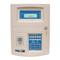
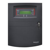
Covers Vigilon Panel Hardware, detailing its physical components and basic structure.
Explains Vigilon Loop Architecture and device addressing processes for Soft and SAFE loops.
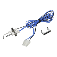
Focuses on S-Quad/S-Cube device identifiers, wiring, optical sensing, and signals.
Details panel menu navigation, card status, loop control, and map interpretation.
Identifies key components visible on the inner door, like LEDs, display, and keypad.
Details the internal components of the Vigilon Plus 24 panel model.
Details the internal components of the Vigilon Plus 72 panel model.
Explains the functions and connections of the Vigilon Plus terminal card.
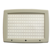
Identifies key components visible on the Compact Plus inner door, like LEDs and keypad.
Details the Compact Plus Main Control Board (MCB) and its features.
Describes the Compact Plus PSU, including its input terminals and fuse details.
Explains the different menu options (Control, Set Up, Info, Test Eng) and their functions.
Guides on how to set the panel's date/time and check the status of installed cards.
Illustrates the typical loop layout and device connection in a Vigilon system.
Explains Soft Addressing and SAFE Addressing for loop devices.
Details procedures for stopping and restarting panel loops.
Covers how to access and interpret loop map data for devices.
Explains how analogue sensors work and how the panel makes fire decisions.
Details how to view device status, including analogue channels and loop information.
Steps for downloading, installing, and setting up the commissioning tool software.
Process for obtaining and applying a licence for the commissioning tool.
How to establish communication between the commissioning tool and the fire panel.
Procedure for downloading panel configuration and saving it as a site file.
How to input site details and assign labels to devices using the tool.
Steps for assigning devices to zones and configuring zone display modes.
Process for uploading configuration to the panel and backing up data to NVM.
Details on creating, managing, and disabling zones and sectors.
Explains how to interpret subfault/exception codes for sensor diagnostics.
Steps for performing routine maintenance, including exception handling.
Practical guide for adding or removing devices on Soft and SAFE addressed panels.
How to view event logs, manage panel passcodes, and use SD card logging.
Procedures for disabling specific devices, zones, or sectors on the panel.
How to use Zone Test Mode for testing devices without triggering system effects.
Introduction to VigInSite, its licences, and capabilities for engineers.
Steps to connect VigInSite to the fire panel and select licences.
Introduction to the LDT, its purpose, compatibility, and licensing.
How to use LDT for panel overview, loop dashboard, and earth fault detection.
Process for generating customer and engineer reports using the LDT.
Explains EN54 Part 23 standards for Visual Alarm Devices (VADs).
Details the classification categories (Ceiling, Wall, Open) for VADs.
Covers VAD coverage data, design tools, and installation drawing requirements.
Important warnings regarding device compatibility, card changes, and NVM initialisation.
Step-by-step instructions for performing a factory reset on the panel.
| Type | Fire Alarm Control Panel |
|---|---|
| Power Supply | 24 V DC |
| Networking | Supports networking with other panels |
| Display | LCD |
| Operating Temperature | 0°C to 40°C |
| Weight | Varies by model |
| Certifications | EN54 |
| Communication | RS485, Ethernet |
| Compatibility | Gent devices |
| Power Supply (Alternative) | Mains power with battery backup |
| Dimensions (Varies) | Depends on configuration |
| Weight (Varies) | Depends on configuration |