TL8100 PROGRAMMABLE THERMOSTAT
69-2017EFS—01 2
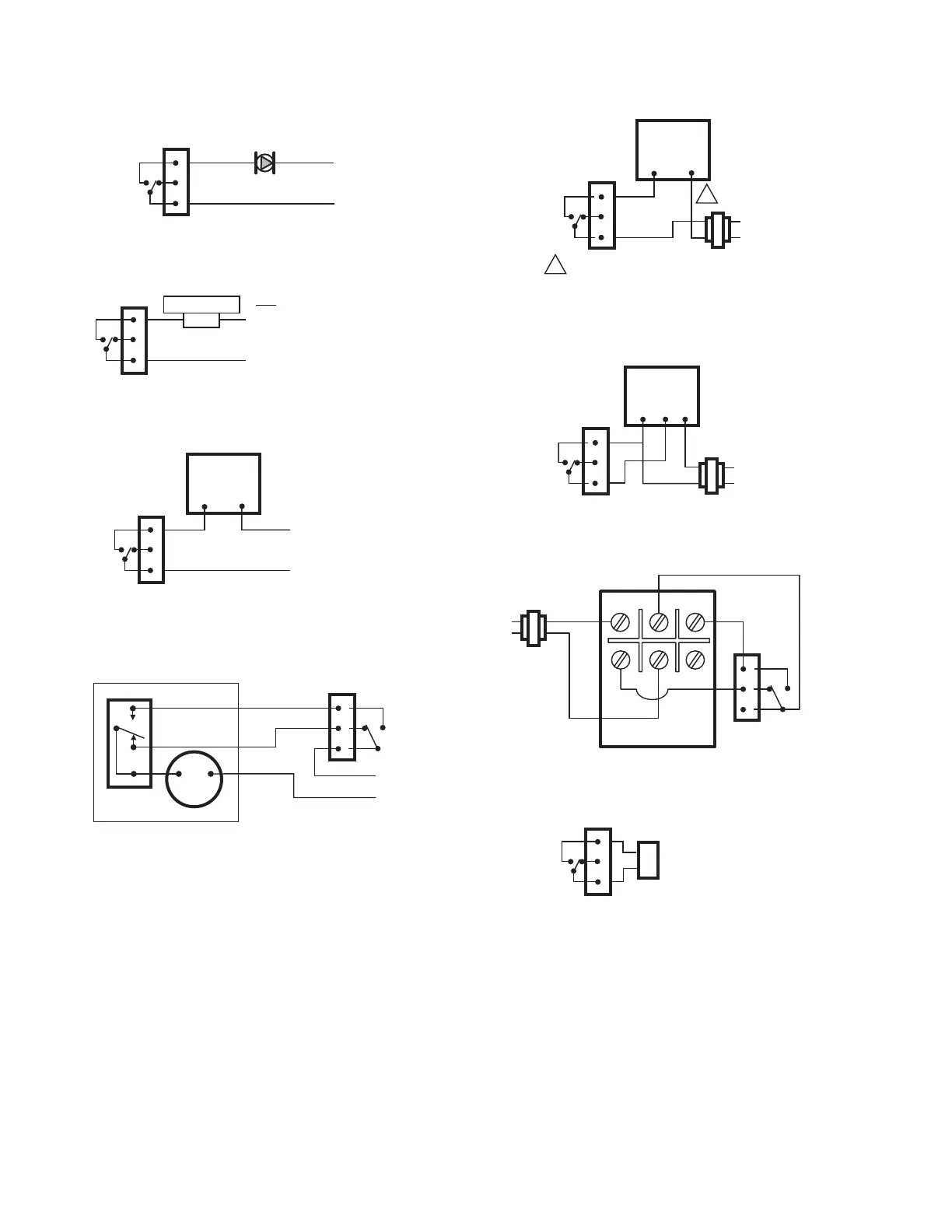
3. THERMOSTAT WIRING
Fig. 3. Wiring diagram for a line voltage circulator.
Fig. 4. Wiring diagram for a line voltage electric heater.
Fig. 5. Wiring diagram for a line voltage valve (V4043 or
similar).
Fig. 6. Wiring diagram for a line voltage 3-wire valve
(V4044 or equivalent); V8044 may be used with 24 VAC
power.
Fig. 7. Wiring diagram for a 24 VAC 2-wire valve
(V8043A,E or equivalent).
Fig. 8. Wiring diagram for a 24 VAC V8043F.
Fig. 9. Wiring diagram for a White Rogers 1311 valve.
Fig. 10. Wiring diagram for a 24 VAC furnace or hydronic
zone panel.
Remote Input Wiring
The thermostat has an input for connecting a home
automation system or a remote control system. When a signal
is received at this input, the thermostat switches to Vacation
mode. When the signal is removed, the thermostat returns to
the original mode. See Fig. 11.
1
3
M29965
L
L
N
120 VAC OR 240 VAC
2 AMP MAXIMUM INDUCTIVE LOAD
2
TL8100
1
3
M29966
L
G
G
N
120/240 VAC
5 AMP MAXIMUM RESISTIVE LOAD
L
N
ELECTRIC HEATER
2
TL8100
1
3
M29967
L
N
120/240 VAC
2 AMP MAXIMUM INDUCTIVE LOAD
2
V4043
L
N
TL8100
1
3
2
M29968
RED
BLUE
YELLOW
MOTOR
V4044 OR V8044
VALVE OPERATOR
L
N
TL8100
1
3
M29977
C
R
2
V8043A, E
L
N
CONNECT BLACK WIRES ON V8043A AND
YELLOW WIRES ON V8043E.
1
1
TL8100
1
3
M29978
C
R
2
V8043F
L
N
TH, TR
TH
TR
TL8100
1
3
2
TL8100
2
5
4
6
1
3
1311
C
R
M29970
L
N
M29971
W
R
FURNACE OR
T, T ON PANEL
1
3
2
TL8100
 Loading...