5 60-2309—8
V4055A,B,D,E
INSTALLATION
INSTALL VALVE
The actuator is mounted directly on the valve bonnet
after the valve is installed in the gas supply line. Refer to the
instructions packed with the gas valve for installation de-
tails. When installing the valve, assure that:
1. Sufficient clearance is left for installation and service
of the actuator.
2. Ambient temperatures at the valve location will re-
main within -40° to 150°F [-40°C to 66°C] or -10°F to 158°F
[-23°C to 70°C] (see Specifications section).
3. Position of the valve permits hookup to the damper if
one is controlled.
INSTALL ACCESSORY SWITCHES (IF NEEDED)
A spdt auxiliary switch may be installed to operate a
load up to 1/2 hp [0.37 kW]. The switch may be adjusted to
operate at any point in the valve stroke.
A proof-of-closure switch may also be installed on any
V4055 actuator to provide a valve seal overtravel interlock
when used with a V5055C or E valve (with double seal).
The spdt proof-of-closure switch is installed to make or
break a circuit when the valve is in the closed position. The
switch is not adjustable.
NOTE: Mark the actuator or valve to indicate any changes
made.
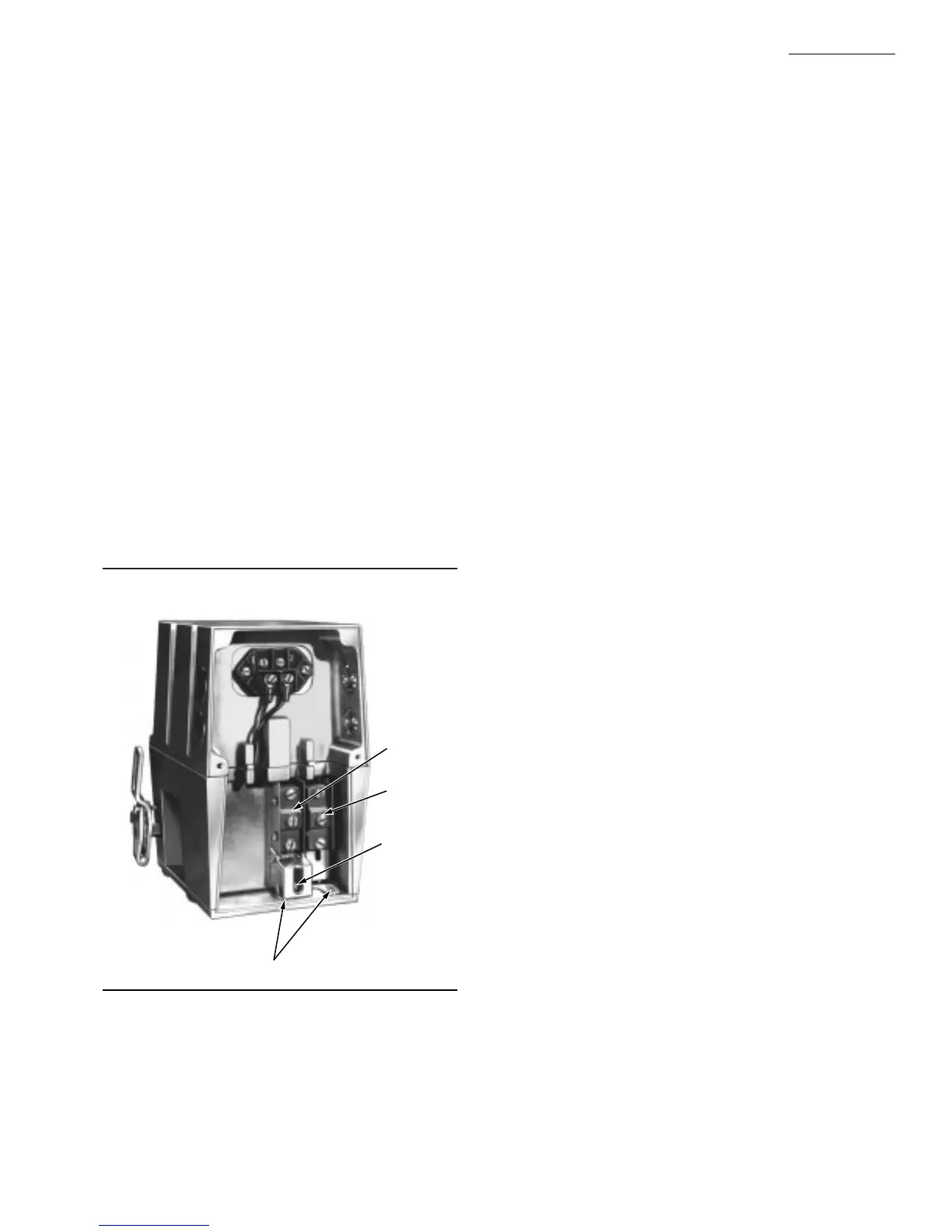
Fig. 2—V4055 Actuator with cover removed.
4. Insert the proof-of-closure switch in the position shown
in Fig. 2. The switch mounts against the side of the actuator
housing. The mounting holes are spaced to mount the switch
only in the correct position. Fasten with two screws through
the actuator base. The proof-of-closure switch is not adjust-
able.
5. If only one switch is used, install the narrow barrier
included with the switch in the unused space.
6. Mount the actuator before making wiring connections
and adjustments to the auxiliary switch.
MOUNT ACTUATOR ON VALVE
Check the final position of the valve body to be sure that
the actuator will be in the proper position when mounted on
the valve. This is especially important if the actuator is used
to drive a damper.
If two smaller sized valves are mounted very closely
together, as in an Industrial Risk Insurers type valve train, it
may be necessary to mount the actuator off center to
provide adequate clearance.
Slip the bottom collar of the actuator over the valve
bonnet assembly. Rotate the actuator to the desired posi-
tion and use a 5/32 inch Allen wrench to securely tighten
the two set screws. (50 to 60 lb/in [5.7 to 6.8 Nm]).
Connect the damper linkage, if used. Refer to the in-
structions packed with the damper arm.
TO REPLACE A V4034 ACTUATOR ON A V5034
VALVE
IMPORTANT: When replacing a standard (26 sec) V4034
actuator on a V5034 Valve, check the main burner
flame-establishing period (MFEP) of the burner pri-
mary safety control. If the MFEP is 10 sec, you must
use a fast-opening (13 sec) V4055 Actuator on the
older V5034 Valve.
The initial action of the V4055 Actuator does not
immediately open the V5034 Valve because of a differ-
ence in stroke length. The pilot may be shut off before
the main burner flame is established. The fast-opening
V4055 Actuator will open the V5034 Valve fast enough
to establish the main burner flame within the ten
second flame-establishing period.
If it is desirable to maintain the slower opening
characteristic of the standard V4034 Actuator, both
the V4034 Actuator and V5034 Valve should be re-
placed. Use a standard V4055 Actuator on a V5055
Valve.
Select the correct adapter, depending on whether the
V5034 has a long or short stem (Fig. 3). Fasten the adapter
to the V5034 Valve bonnet, and then mount the actuator on
the adapter. Follow the instructions for mounting the actua-
tor on the valve.
If the V4034 being replaced is equipped with a heater,
there will be a low limit control connected in series with the
V4034 power supply to prevent actuator operation below
25°F [-4°C]. There will also be a constant source of the line
voltage power to the heater and its control thermostat.
133568
AUXILIARY
SWITCH
133569
PROOF-OF-
CLOSURE
SWITCH
EACH SWITCH
SECURED BY TWO
SCREWS FROM
BOTTOM OF BASE.
ADJUSTING
SCREW FOR
AUXILIARY
SWITCH
IF ONLY ONE SWITCH IS
USED, INSTALL BARRIER
IN OPEN POSITION.
M7326
To install the switches, proceed as follows:
1. Remove the actuator faceplate (two screws).
2. Remove the sliver-colored barrier to expose the actua-
tor stem.
3. Insert the auxiliary switch in the position indicated in
Fig. 2. Fasten with two screws through the actuator base.
 Loading...