60-2309—8 6
V4055A,B,D,E
INSTALLATION
The V4055 is rated for ambient temperature down to -
40°F [-40°C] for 60 Hz models, or -10°F [-23°] for 50 Hz
and 50/60 Hz models, and does not require a heater. Re-
move all the wiring associated with the heater. Disconnect
the power supply for the heater at its source and remove the
wires. See Fig. 4.
Fig. 4—Remove heater circuits, if installed,
when replacing V4034 Actuator.
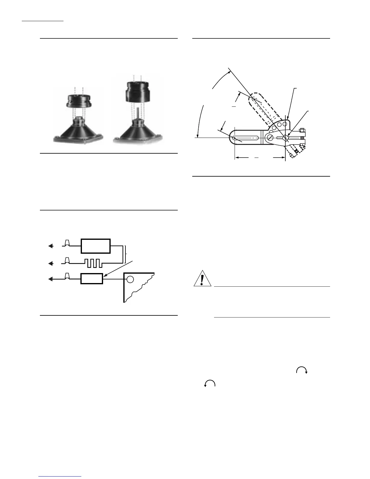
Fig. 5—7616BR Damper Crank Arm may be
attached to actuator shaft to drive a damper
when valve is opened.
52 DEGREE
ANGULAR
ROTATION
MAXIMUM
TRAVEL
SHAFT
7616BR
DAMPER
ARM
M7322
1
11
16
2
5
16
[68]
RADIUS
[59]
WIRING
Disconnect power supply before making electrical con-
nections to prevent electrical shock or equipment damage.
Wiring must comply with all applicable electrical codes,
ordinances, and regulations. Wiring to the actuator must be
NEC Class 1.
Connect the power supply to terminals 1 and 2 on the
V4055 terminal strip. Refer to Fig. 6 for auxiliary switch
connections. For typical system hookups, refer to Fig. 7
and to instructions packed with device used to control
valve.
When all wiring connections are complete, replace the
actuator faceplate.
CAUTION
Label all wires prior to disconnection when servic-
ing values.Wiring errors can cause improper and
dangerous operation.
Verify proper operation after servicing.
NOTE: Pipe sealant is required on the conduit threads of
actuators with NEMA 4 enclosures.
ADJUST THE AUXILIARY SWITCH (IF USED)
The auxiliary switch is adjustable throughout the stroke
of the actuator. With the switch installed in the actuator,
turn the adjusting screw (Fig. 2) clockwise to cause
the switch to operate earlier in the stroke or counterclock-
wise to cause the switch to operate later in the stroke.
NOTE: The proof-of-closure switch is not adjustable.
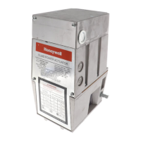
Fig. 3—Adapters permit use of V4055 Actuator
with V5034 Valve.
USE NO. 133533A
ADAPTER WITH
SHORT STEM V5034
USE NO. 133534A
ADAPTER WITH
LONG STEM V5034
M7325
1
HEATER
THERMOSTAT
LOW
LIMIT
HEATER
CIRCUIT
HEATER
L1
(HOT)
TO MAIN
VALVE TERMINAL
ON BURNER CONTROL
L2
BLACK
WHITE
REMOVE HEATER CIRCUIT
COMPLETELY AND
REMOVE LOW LIMIT
V4034
M7333
MOUNT AND ADJUST 7616BR DAMPER CRANK
ARM (IF USED)
IMPORTANT: When a damper crank arm is used with a
NEMA 4 actuator that is exposed to ice or sleet, a
suitable shield must be installed to prevent ice or sleet
buildup.
Follow installation and adjustment directions included
with damper crank arm. Maximum pushrod travel is 2-5/16
in. [58.7 mm] through a stroke of 52 degrees. See Fig. 5.
 Loading...