68-0049—2 6
VR8205; VR4205
INSTALLATION␣ ␣ ␣
Fig. 4—Use moderate amount of pipe com-
pound.
Fig. 5—Top view of gas control.
OUTLET
PRESSURE
TAP
INLET
OUTLET
INLET
PRESSURE TAP
PRESSURE REGULATOR
ADJUSTMENT (UNDER
CAP SCREW)
GAS CONTROL KNOB
M9061
GAS CONTROL KNOB
VR4205
CONDUIT
COVER
OUTLET
PRESSURE
TAP
INLET
OUTLET
WIRING
TERMINALS (2)
INLET
PRESSURE TAP
PRESSURE REGULATOR
ADJUSTMENT (UNDER
CAP SCREW)
VR8205
VR4205
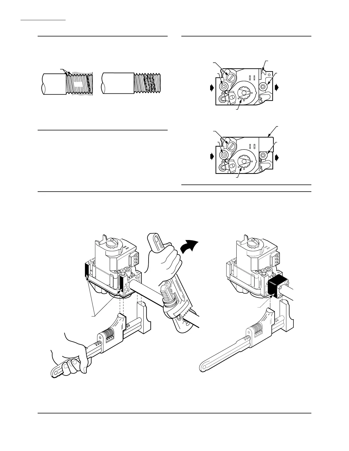
5. Remove seals over control inlet and outlet if neces-
sary.
6. Connect pipe to control inlet and outlet. Use wrench
on the square ends of the control. If an adapter is used, place
wrench on adapter rather than on control. Refer to Figs. 5
and 6.
TWO IMPERFECT
THREADS
GAS CONTROL
THREAD PIPE THE AMOUNT
SHOWN IN TABLE 4 FOR
INSERTION INTO GAS CONTROL
APPLY A MODERATE AMOUNT OF
PIPE COMPOUND TO PIPE ONLY
(LEAVE TWO END THREADS BARE).
M3075A
PIPE
Fig. 6—Proper use of wrench on gas control with and without flanges.
APPLY WRENCH
FROM TOP OR
BOTTOM OF GAS
CONTROL TO
EITHER SHADED AREA
WHEN FLANGE IS NOT USED
APPLY WRENCH
TO FLANGE ONLY
WHEN FLANGE IS USED
M3079
 Loading...


