9 68-0049—2
VR8205; VR4205
STARTUP AND CHECKOUT
Slow-opening and Step-opening Pressure Regulators
1. Check the full rate manifold pressure listed on the
appliance nameplate. Gas control full rate outlet pressure
should match this rating.
2. With main burner operating, check gas control flow
rate using the meter clocking method or pressure using a
manometer connected to the outlet pressure tap on the gas
control. See Fig. 5.
3. If necessary, adjust pressure regulator to match ap-
pliance rating. See Table 5A or 5B for factory set nominal
outlet pressure and adjustment setting range.
a. Remove pressure regulator adjustment screw.
b. Using screwdriver, turn inner adjustment screw
clockwise to increase or counterclock-
wise to decrease gas pressure to burner.
c. Always replace cap screw and tighten firmly to
prevent gas leakage.
4. If desired outlet pressure or flow rate cannot be
achieved by adjusting the gas control, check gas control
inlet pressure using a manometer at the gas control inlet
pressure tap. If inlet pressure is in the nominal range (see
Table 5A or 5B), replace gas control. Otherwise, take the
necessary steps to provide proper gas pressure to the con-
trol.
5. STEP-OPENING PRESSURE REGULATORS
ONLY. Carefully check burner lightoff at step pressure.
Make sure burner lights smoothly and without flashback to
orifice. Make sure all ports remain lit. Cycle burner several
times, allowing at least 30 seconds between cycles for
regulator to resume step function. Repeat after allowing
burner to cool. Readjust full rate outlet pressure, if neces-
sary, to improve lightoff characteristics.
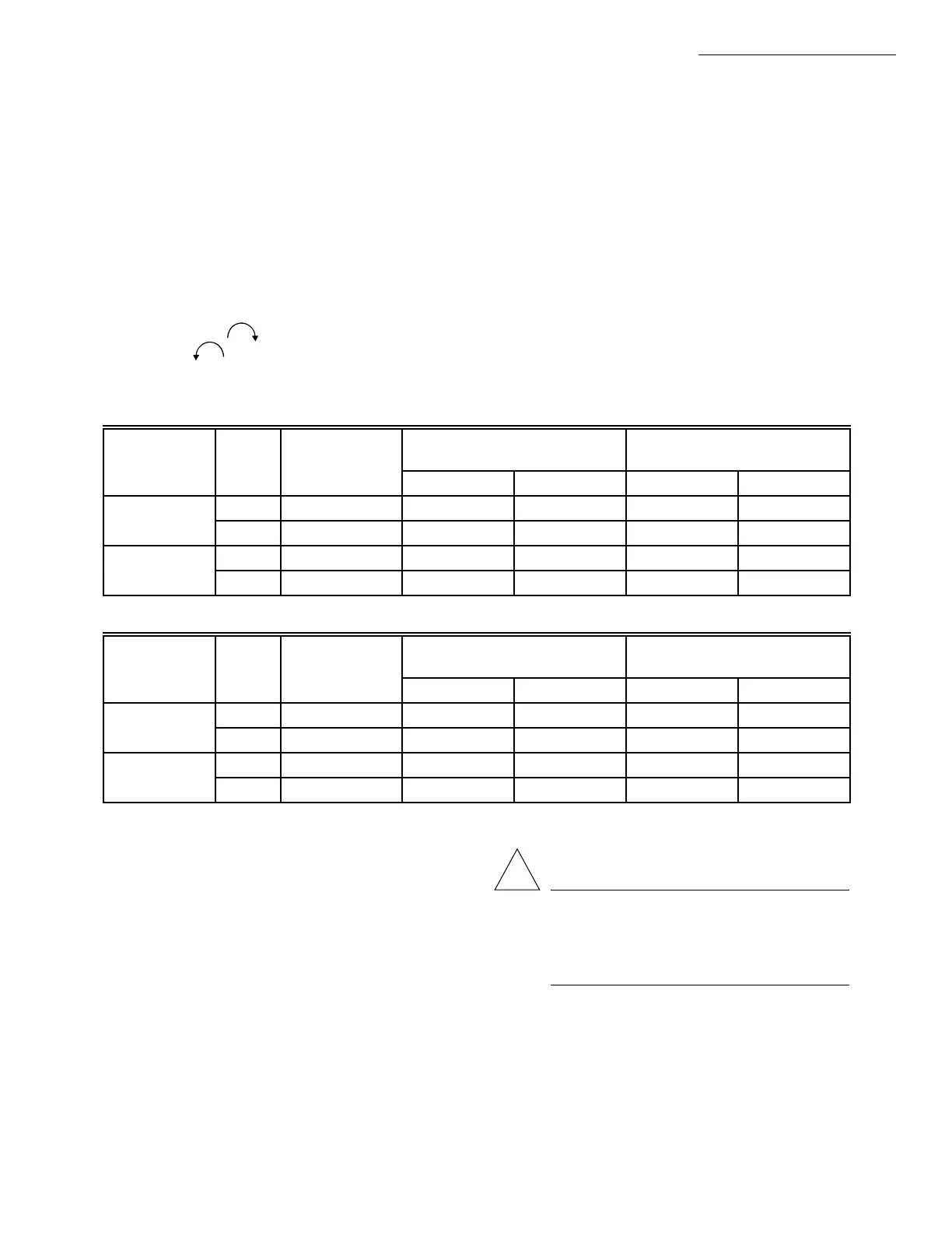
TABLE 5A—PRESSURE REGULATOR SPECIFICATION PRESSURES (in. wc)
Model Type Nominal Inlet
Factory Set
Nominal Outlet Pressure Setting Range
Type of Gas Pressure Range
Step Full Rate Step Full Rate
Standard,
Natural 5.0 - 7.0 — 3.5 — 3.0 - 5.0
slow-opening
LP 12.0 - 14.0 — 10.0 — 8.0 - 12.0
Step-opening Natural 5.0 - 7.0 0.9 3.5 — 3.0 - 5.0
LP 12.0 - 14.0 2.2 10.0 — 8.0 -12.0
TABLE 5B—PRESSURE REGULATOR SPECIFICATION PRESSURES (kPa).
Model Type Nominal Inlet
Factory Set
Nominal Outlet Pressure Setting Range
Type of Gas Pressure Range
Step Full Rate Step Full Rate
Standard,
Natural 1.2 - 1.7 — 0.9 — 0.7 - 1.2
slow-opening
LP 2.9 - 3.9 — 2.5 — 2.0 - 3.0
Step-opening Natural 1.2 - 1.7 0.2 0.9 None 0.7 - 1.2
LP 2.9 - 3.9 0.9 2.5 None 2.0 - 3.0
CHECK SAFETY LOCKOUT
(SLOW-OPENING CONTROLS ONLY)
1. With the system power off and the thermostat set to
call for heat, manually shut off the gas supply.
2. Energize ignitor control and start timing safety lock-
out time. When spark ignition terminates, stop timing.
When using the VR8205H or VR4205H step-opening
control, the specified ignitor control safety lockout time
must exceed 8.5 seconds for system to function properly.
3. After spark cutoff, manually reopen gas control knob.
No gas should flow to the main burner.
4. Reset system by adjusting thermostat below room
temperature, waiting 30 seconds, and moving thermostat
setting up to call for heat. Normal ignition should occur.
CHECK SAFETY SHUTDOWN PERFORMANCE
WARNING
FIRE OR EXPLOSION HAZARD
CAN CAUSE PROPERTY DAMAGE,
SEVERE INJURY OR DEATH
Perform the safely shutdown test any time work is
done on a gas system.
NOTE: Read steps 1-7 below before starting and compare
to the safety shutdown or safety lockout tests recom-
mended for the direct ignition (DI) module. Where they
differ, use the procedure recommended for the module.
!
 Loading...


