Chapter 6 – Maintenance
Honeywell Confidential: Use or disclosure of information on this page is subject to the restrictions on the title page.
13841 Rev A
233
Main PCB (PCB/graphics module
assembly); For 13590-2:
For 13590-3 and 14990:
Washer, fiber, 0.5-in. inner diameter,
1.0-in. outer diameter
Screw lock, 4-40 by 3/8 in.
Washer No. 4, lock split ring
Fuse, 2a, 125V, PCB; part of battery
contact PCB assembly
EPROM (programmed integrated
circuit, No. 27C2048) for 13590-2
only
6.3.7.2
Disassembly
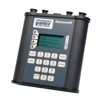
Disassemble the Vibrex unit, as follows:

 Loading...


