vi
List of Figures
•••••••••••••••••••••••••••••••••••••••••••••••••
Figure 1-1: Isolating Fire Devices from Burglary Devices.....................................................................................................1-4
Figure 3-1: Installing the Lock...............................................................................................................................................3-1
Figure 3-2: Cabinet Attack Resistance Considerations ........................................................................................................3-2
Figure 3-3: Commercial Fire Installation Considerations ....................................................................................................3-2
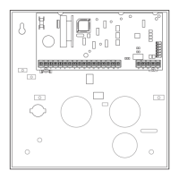
Figure 3-4: Mounting the PC Board.......................................................................................................................................3-3
Figure 3-5: Keypad Connections to Control Panel ................................................................................................................3-4
Figure 3-6. ECP Isolator Wiring .............................................................................................................................................3-4
Figure 3-7: Intentionally Left Blank......................................................................................................................................3-4
Figure 3-8: Wiring Auxiliary Relay for Alarm Activation.....................................................................................................3-8
Figure 3-9: Wiring Auxiliary Relay for Smoke Detector Reset.............................................................................................3-8
Figure 3-10: 2-Wire Smoke Detector on Zone 1 (for zone 2 use terminals 17 and 18).......................................................3-11
Figure 3-11: 4-Wire Smoke Detectors ..................................................................................................................................3-12
Figure 3-12. Wiring Latching Glassbreaks to Zone 8...........................................................................................................3-13
Figure 3-13: Wiring a Normally Closed Sensor Loop for Tamper Supervision..................................................................3-13
Figure 3-14: Wiring a Normally Open Sensor Loop for Tamper Supervision....................................................................3-14
Figure 3-15: Polling Loop Connections to the Control Panel..............................................................................................3-16
Figure 3-16: Polling Loop Connections Using One 4297 Extender Module .......................................................................3-16
Figure 3-17: Polling Loop Connections Using Multiple Extender Modules .......................................................................3-17
Figure 3-18: Installing the 5881ENHC with Tamper Protection ........................................................................................3-19
Figure 3-19: 5881/5883 RF Receiver (cover removed) .........................................................................................................3-19
Figure 3-20: 4204 Relay Module...........................................................................................................................................3-21
Figure 3-21: 4204CF Relay Module......................................................................................................................................3-22
Figure 3-22: Remote Keyswitch Wiring ...............................................................................................................................3-23
Figure 3-23: Remote Keypad Sounder Wiring.....................................................................................................................3-23
Figure 3-24: Wiring Communicator to Keypad Terminals .................................................................................................3-25
Figure 3-25: Connecting the Backup Batteries ....................................................................................................................3-30
Figure 7-1: Direct-Wire Downloading Connections.............................................................................................................7-16
VISTA-128FBPN Summary of Connections Diagram...................................................................................Inside Back Cover

 Loading...
