∗
∗∗
∗29 Internal Device Menu Mode
(for Programming IP and GSM Module Options)
This mode is for programming the Internet connection (IP) and GSM Module
configuration, collectively referred to as the Internal Device.
NOTE: The Internal Device is automatically set to address 3 and cannot be
changed.
IMPORTANT: The use of the IP connection or the VISTA-GSM module
requires an AlarmNet–I account. Please obtain the account information
from the central station prior to programming this module.
The following section describes the programming of the internal device
options using an alpha keypad. Alternatively, these options can be
programmed via the AlarmNet Direct website. After programming is
complete, the control must be registered with AlarmNet (via the control’s
RJ45 Internet connection). Refer to the Registration with AlarmNet section
for procedures.
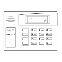
Using an Alpha Keypad as a 7720P Programming Tool
When programming IP/GSM features (with ∗29 menu mode), the alpha
keypad mimics the functions of the 7720P Programming Tool. See figure at
right and table below for 7720P key functions. Each key has two possible
functions: a normal function and a SHIFT function.
Normal functions: The numeric values labeled directly on the keys and
the left-hand functions shown in diagram on the ABC keys. To perform a
normal key function, simply press the desired key.
SHIFT functions: Those functions shown in diagram above the numerical
keys and the right-hand functions shown on the ABC keys. To perform a
SHIFT key function, press SHIFT key (D key), then press the desired
function key (shift function is indicated by the lit READY LED).
7720P Emulation Template for Alpha Keypads
1
OFF
4
MAX
7
INSTANT
READY
2
AWAY
5
TEST
8
CODE
0
3
STAY
6
BYPASS
9
CHIME
(B)
A
D
S
ENTER
SHIFT
N / Y
/
BS/ESC
SPACE
B
E
T
C
F
X
#
ARMED
READY
6160-7720P-001-V0
SHIFT
FUNCTION
WHEN LIT
(C)
(D)
(A)
Normal and SHIFT key Functions While in ∗
∗∗
∗29 Menu Mode
Key Normal Key Function SHIFT Key Function
(A) = BS/ESC [BS]: Press to delete entry [ESC]: Press to quit Program Mode
Also, can reset EEPROM defaults
†
(B) = ↓/↑ [↓]: Scroll down programming [↑]: Scroll up programming
(C) = N/Y [N]: Press for "NO" answer [Y]: Press SHIFT-Y for "YES" answer
(D) = SHIFT Press before pressing a SHIFT key function. Will light READY LED. LED goes out once a key is pressed. Press again for
each SHIFT function desired.
1/A [1]: For entering the number 1 [A]: Used for entering C.S. ID number
2/B [2]: For entering the number 2 [B]: Used for entering C.S. ID number
3/C [3]: For entering the number 3 [C]: Used for entering C.S. ID number
4/D [4]: For entering the number 4 [D]: Used for entering C.S. ID number
5/E [5]: For entering the number 5 [E]: Used for entering C.S. ID number
6/F [6]: For entering the number 6 [F]: Used for entering C.S. ID number
7/S [7]: For entering the number 7 [S]: Press to display diagnostic status
8/T [8]: For entering the number 8 [T]: Press to send TEST messages
9/X [9]: For entering the number 9 [X]: Press to reset the IP/GSM
[∗] / SPACE [∗]: Used to select programming options
[SPACE]: Not used
0 [0]: For entering the number 0
[#] / ENTER [#] / ENTER: Press to accept entries No SHIFT function
†
Active only when the "REVIEW?" prompt is displayed
Internal Device (IP and GSM) Default Values
The programming default values for ∗29 Menu Mode are listed in the Table below.
OPTION STANDARD DEFAULT VALUE ACTUAL ENTRY
1 Internal Device IP
2 Primary City ID ??
3 Primary CS ID ??
4 Primary Sub ID ????
5 Supervision 24 Hours
6 GSM Rollover Y/N N (if GSM enabled)
7 GSM 24Hr Tst Y/N N (if GSM enabled)
8 Old Alarm Time 10 Minutes
9 IP Fault Time 00 Minutes
10
GSM Fault Time 00 Minutes (if GSM enabled)
11
Notify Panel Of Neither Fault (if IP and GSM enabled)
12 Use DHCP Y/N Y (if IP or IP/GSM enabled)
13 NIC IP Address 255.255.255.255 (if DHCP not used)
14 Subnet Mask 255.255.255.255 (if DHCP not used)
15 Gateway IP Addr 255.255.255.255 (if DHCP not used)
16 DNS IP Addr. 255.255.255.255 (if DHCP not used)
Status and Contact ID Reporting Codes
The Internal Device (IP/GSM) sends status messages to the control panel for network connectivity failures. Trouble messages are displayed on the keypad as
“Check 103,” with status displayed as “LngRng Radio” followed by a 4-digit keypad display status code, defined below.
Keypad Display Status Codes
CODE DESCRIPTION
0000 Control panel lost communication with internal device
0005 internal device has lost contact with AlarmNet network
000F internal device is not registered; account not activated
0019 GSM module shut down
0400 internal device Power-on reset
** reports only if IP and GSM enabled
Contact ID Codes (as displayed at 685) sent to CS via IP/GSM
CODE DESCRIPTION
E339 C803 Power-on reset
E350 C951 Primary communication path failure (Ethernet)**
R350 R951 Primary communication path restore (Ethernet)**
E350 C952 Secondary communication path failure (GSM)**
R350 C952 Secondary communication path restore (GSM)**
E355 C000 Module lost ECP communication with control
R355 C000 Module restore ECP communication with control
E353 C103 Long range transmitter fault trouble
R353 C103 Long range transmitter fault restore
– 12 –
WWW.DIYALARMFORUM.COM
 Loading...