SOLID STATE ECONOMIZER SYSTEM
63-2484—03 12
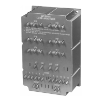
Fig. 16. Mounting the W7212 module on sheet metal.
C7400 Enthalpy Sensor and C7660
Temperature Sensor Location and
Mounting
Outdoor air sensing: Mount the C7400 Enthalpy Sensor or
C7660 Temperature Sensor in any orientation where it is
exposed to freely circulating air but protected from rain, snow
and direct sunlight.
Return air sensing: For differential enthalpy control, a second
C7400 Enthalpy Sensor is connected to the W7459 or W7212.
Mount the second sensor in the return air duct as far as
possible from the outdoor air sensor. C7400A sensors are
used with W7212A, W7213, and W7214 economizers. The
C7400C is used with W7212C economizers.
Wiring
Can Cause Electrical Shock or Equipment
Damage.
Disconnect power supply before connecting wiring.
Disconnect the power supply before connecting wiring to
prevent electrical shock or equipment damage. All wiring must
comply with applicable local codes, ordinances and
regulations.
OPERATION AND CHECKOUT
C7046C (Discharge) and C7150B (Mixed)
Air Sensors
The C7046C discharge air sensor is applied following the coils
in the supply air to the conditioned space. The C7150B mixed
air sensor is mounted in the mixing box, where the “best”
combination of outdoor and return air temperature can be
measured. Use either a discharge or a mixed air sensor to
provide input to the economizer module through T and T1
Terminals.
Fig. 17. C7046C and C7150B Air Temperature Sensors
resistance versus temperature.
C7400 Solid State Enthalpy Sensor
The C7400 Solid State Enthalpy Sensor is used with a solid
state economizer control and damper actuator to proportion
an outdoor air damper in a ventilation system.
Figure 18 is a partial psychrometric chart with single C7400A
Sensor and W7459A Economizer Logic Module performance
curves. The curves illustrate the reset in the temperature
control point due to changes in relative humidity.
Figure 19 is a partial psychrometric chart with single C7400C
sensor and W7212C economizer logic module performance
curves. Note the C7400C and W7212C have the additional E
curve.
The enthalpy control setpoint A, B, C, or D combines
temperature and humidity conditions, resulting in the control
curve shown in Fig. 18. When the enthalpy or outdoor air is
below (left of) the appropriate curve, the outdoor air damper
can proportion open on a call for cooling. If outdoor air
enthalpy rises above (to the right of) the control curve, the
outdoor air damper closes to the minimum position.
For differential enthalpy, turn the control setpoint to D (fully
clockwise). If outdoor air enthalpy is lower than return air
enthalpy, the outdoor air damper proportions open on a call for
cooling.
If outdoor air is higher enthalpy than return air enthalpy, the
outdoor air damper closes to minimum position. Differential
enthalpy control provides energy savings and increased
comfort by using the air with the lowest enthalpy.
If outdoor air enthalpy and return air enthalpy are equal, the
outdoor air damper proportions open on a call for cooling.
The relationship between the C7400A Sensor output current
and relative humidity is shown in Fig. 20.
The relationship between the C7400C sensor output current
and relative humidity is shown in Fig. 22.
4500
4000
3500
3000
2500
2000
1500
1000
55
60 65 70 75 80 85 90 95 100
15
20
25
30 35
RESISTANCE (OHMS)
TEMPERATURE (DEGREES)
M9099
F
C
3,000 OHMS AT
77F (25C)
 Loading...