Do you have a question about the Honeywell W7080A and is the answer not in the manual?
Provides SPDT relay switching for heating/cooling stages and modulating output.
Uses M745K/M745L motor for first stage cooling with outdoor air.
System switches stages off upon power interruption and on upon restoration.
Power supplies are short-circuit protected against 24 Vdc shorts.
Enables night setback and cooling shut-down for zones via a time clock.
Details various system components including sensors, thermostats, limit controllers, and analyzers.
Covers voltage, frequency, power consumption, and SPDT relay contact ratings.
Lists DC voltage signals for system inputs and outputs with relevant components.
Explains stage differentials and thermostat dead band settings as depicted in Figure 1.
Outdoor air damper modulation based on mixed air temperature setpoint.
Selectable minimum output for fan motor speed control.
Defines how zone discharge sensor changes affect voltage.
Specifies operating and shipping temperature ranges.
Limits cold deck temperature to selectable setpoints.
Limits hot deck temperature to selectable setpoints.
Guidelines for transformer use, isolation, and grounding.
Descriptions of damper linkage, valve linkage, and potentiometers.
Guidance on using valves with Super Modutrol motors.
Lists resistor values for achieving specific heating setbacks.
Details on the metal cover for protecting system components.
The Honeywell Multizone Control System is a solid-state system designed for component field replacement of the Ranco EA3 Lodapt System. It provides comprehensive control for multizone HVAC applications.
The basic system controls up to 12 zone dampers, 3 heating stages, 3 cooling stages, an integrated economizer, and modulating valves for hot and chilled water. Optional units can expand control to include up to 12 additional zones, 5 stages of electric heat, a variable air volume (VAV) system fan, and a fourth stage of cooling.
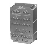
The W7080A Load Analyzer (Ranco EA3) is a central component, providing SPDT relay switching for three stages of heating and three stages of cooling. It also delivers a modulating output to economizer and valve motors, responding to the highest heating and cooling demand from zone thermostats. The analyzer serves as the source of 24 Vdc power for zone thermostats and sensors.
Zone dampers are directly controlled by a modulated DC voltage signal from the zone thermostat, which is modified by a zone discharge sensor. Pilot duty SPDT relays manage heating and cooling stages.
The economizer utilizes an M745K or M745L motor to provide true first-stage cooling, prioritizing outdoor air whenever possible. The system is designed to switch all stages off upon power interruption and switch all stages on when power is restored. Compressor turn-on time delays must be incorporated for each compressor.
Power supplies within the W7080A Load Analyzer and W7084A Zone Adder are short-circuit protected, meaning short circuits of 24 Vdc from either unit will not damage their power supplies. Night setback and cooling shut-down for individual or all zones can be achieved by adding a time clock.
| Brand | Honeywell |
|---|---|
| Model | W7080A |
| Category | Control Systems |
| Language | English |