EasyManua.ls Logo

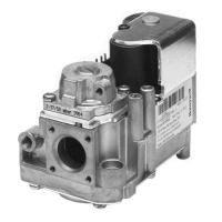
Honeywell vk41 series

Honeywell vk41 series
34 pages
To Next Page IconTo Next Page
Loading...
PRODUCT HANDBOOK
1 EN2R-9004 0606R20-NE
Subject to change without notice. All rights reserved.
VK41../VK81..SERIES
GAS CONTROLS FOR COMBINED VALVE AND IGNITION SYSTEM
APPLICATION
The Combined Valve and Ignition (CVI) system has been
developed for application in gas fired domestic central heating
boilers, combi boilers and warm air furnaces or water heater
appliances with an automatic ignition system.
For this system, the VK41../VK81.. series gas controls have
been designed to have the S4565/S4575/S4585 series
ignition control attached directly on to the valve.
The combined system then provides programmed safe light
up, flame supervision and regulation of gas flow to the main
burner and/or pilot burner of the appliance.
The VK41.5/VK81.5 series gas controls (without pilot outlet)
can also be used alone in direct burner ignition applications.
A plug (order number 45.900.441- ) with integrated rectifier
circuit then has to be used on the gas control.
Contents
General page
Description ...................................................................... 2
Features .......................................................................... 3
Dimesional ..................................................................... 4
Application ...................................................................... 6
Technical
Specifications .................................................................. 7
Electrical data .............................................................. 10
Capacity curves ....................................................... 13-18
Performance characteristics .......................................... 19
Installation ..................................................................... 21
Electrical connections and wiring .................................. 24
Adjustments and checkout ............................................ 25
Construction and working principles ............................. 26
Various
Quality assurance statement ......................................... 29
Standards and approvals .............................................. 30
Ordering information ..................................................... 31
Replacement parts and accessories ............................. 32
Question and Answer IconNeed help?

Do you have a question about the Honeywell vk41 series and is the answer not in the manual?

Honeywell vk41 series Specifications

General IconGeneral
BrandHoneywell
Modelvk41 series
CategoryControl Systems
LanguageEnglish

Summary

APPLICATION

DESCRIPTION

FEATURES

DIMESIONAL DRAWING STANDARD CONNECTION

DIMESIONAL DRAWING EXTERNAL THREAD CONNECTION

SPECIFICATIONS

Minimum differential pressure

Specifies minimum differential pressure for different models.

Maximum operating pressure

Details maximum operating pressure and inlet pressure limits.

Outlet pressure range for ONOFF regulators

Defines outlet pressure adjustment range for ON/OFF regulators.

Minimum regulation capacity

States the minimum regulation capacity in m³/h air.

Mounting holes

Describes mounting hole specifications for flanges and screws.

CAPACITY

CAPACITY CURVE H10 (CVI)

Graphs pressure drop vs. flow for H10 CVI models.

CAPACITY CURVE H20 (CVI)

Graphs pressure drop vs. flow for H20 CVI models.

CAPACITY CURVE H140 (CVI)

Graphs pressure drop vs. flow for H140 CVI models.

CAPACITY CURVE H150 (CVI)

Graphs pressure drop vs. flow for H150 CVI models.

CAPACITY CURVE H160 (CVI)

Graphs pressure drop vs. flow for H160 CVI models.

CAPACITY CURVE H170 (CVI)

Graphs pressure drop vs. flow for H170 CVI models.

ELECTRICAL DATA

Fig. 1. Coil connection

Illustrates coil connection points for gas controls.

Fig. 2. Mounting of rectifier plug

Shows the method for mounting a rectifier plug.

PERFORMANCE CHARACTERISTICS

Maximum allowable leakage

Specifies factory tested leakage requirements for gas controls.

Outlet pressure adjustment range capability

Details pressure adjustment range for different gas types.

Minimum adjustable capacity

States minimum adjustable capacity for throttle valve versions.

Pilot flow

Specifies pilot flow capacity and pressure drop.

Recovery time of servo system

Defines recovery time for the adjustable SOFTLITE system.

High pressure test

Describes withstand capability to inlet pressure under 'OFF' condition.

Operable voltage range

Details the voltage range for satisfactory gas control function.

Valve closing characteristics

Specifies time for gas control to close after operator de-energization.

Main valve opening characteristics (measured with gas)

Details fast and SOFTLITE opening characteristics.

SOFTLITE versions

Provides adjusted outlet pressure for SOFTLITE versions.

INSTALLATION

Gas controls with internal thread

Instructions for connecting gas controls with internal threads.

Gas controls for flange connection

Steps for mounting gas controls using flange connections.

Gas controls with external thread connection

Guidance for connecting gas controls with external threads.

ELECTRICAL CONNECTIONS AND WIRING

Wiring

Guidelines for using appropriate cables and insulation.

Assembling of the cable connector(s) for IP 20 protection

Steps for assembling cable connectors for IP 20 protection.

Assembling of the cable connector(s) for IP 44 protection

Procedure for assembling cable connectors for IP 44 protection.

Assembly of cover with integrated strain relief

Instructions for attaching the cover with strain relief.

Disassembly of cover with integrated strain relief

Steps for removing the cover with integrated strain relief.

Fusing

Information on integral fuses in ignition controls.

Spark gap

Specifies the maximum allowable spark gap.

Supply voltage polarity

Warning regarding correct polarity for ignition controls.

Checking flame current

Procedure for checking flame current and troubleshooting.

ADJUSTMENTS AND CHECKOUT

Pressure tap

Instructions for using pressure taps for checks.

Pilot flame (VK4100 VK8100 only)

Notes on pilot flame ignition timing after long stoppages.

Outlet pressure adjustment onoff versions

Procedure for adjusting outlet pressure for on/off versions.

Outlet pressure adjustment throttle versions VK.1..ET

Procedure for adjusting flow for throttle versions.

Check of SOFTLITE

How to check SOFTLITE performance and burner ignition.

SOFTLITE adjustment

Instructions for adjusting SOFTLITE pressure and gas types.

Throttle adjustment..VE types.

How to adjust the throttle screw for VE types.

Final checkout of the installation

Steps for final checks after adjustments and operation.

Maintenance and service

Information on maintenance and sealed screws.

CONSTRUCTION AND WORKING PRINCIPLES

Servo pressure regulation

Explains the servo pressure regulation mechanism.

SOFTLITE

Details the SOFTLITE mechanism for improved ignition and flame control.

Fig. 15. Opening characteristics

Graphs comparing fast open vs. SOFTLITE opening characteristics.

SOFTLITE adjustment

Explains how to adjust SOFTLITE settings for different pressures.

Fig. 17. Safety valve and main valve open position

Diagram showing safety and main valve open positions.

Fig. 18. Adjustable SOFTLITE

Graphs showing outlet pressure curves for adjustable SOFTLITE.

QUALITY ASSURANCE STATEMENT

STANDARDS AND APPROVALS

ORDERING INFORMATION

Fig. 19. Model number chart VK series gas controls

Chart for specifying VK series gas control model numbers.

REPLACEMENT PARTS AND ACCESSORIES

Flange Assemblies

List of flange assemblies with connection sizes and order numbers.

Fitting

Details compression and pressure feedback fittings with order numbers.

Related product manuals