EN2R-9004 0606R20-NE 8
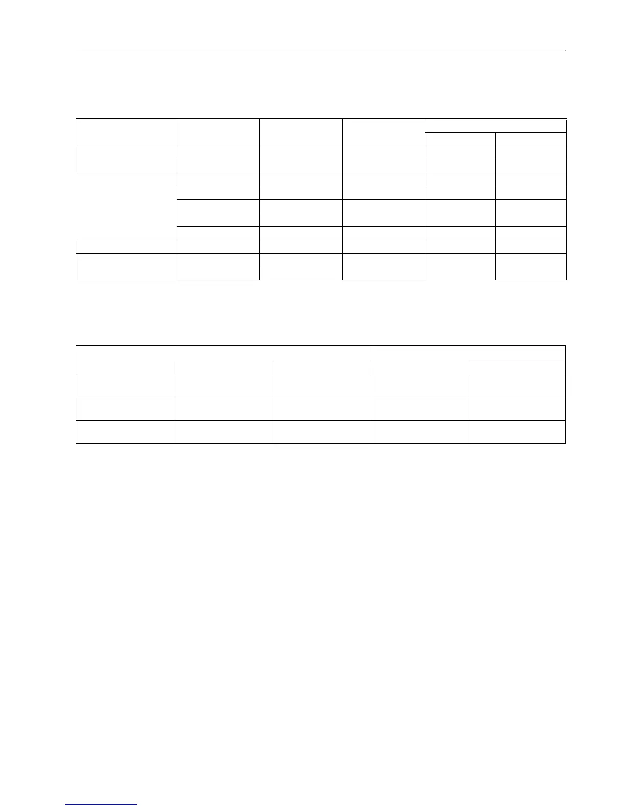
Capacity
In m
3
/h air at pressure drop as shown below. See also the capacity curves concerned.
NOTE 1.: Versions with side outlet connection have a 0.2 m
3
/
h
air lower capacity.
NOTE 2.: Increased capacity versions are optional for types with suffix letter E, T and V.
NOTE 3.:
3
/
4
“ external thread versions have a 0.3 m
3
/
h
air lower capacity.
Model Extention ∆P (mbar) Capacity (m
3
/h air) Capacity curve
Number Page
VK410X/VK810X A, B, C, D, M, N, P, Q 3 3.4 H 10 13
E, T 3 2.8 H 160 17
VK411x/VK811x A, B, C, D, M, N, P, Q 5 4.4 H 20 14
E, T 5 3 H 170 18
V, VE 5 3.4 H 140 15
10 5.1
VB 5 4.4 H 20 14
VK412X A, B, C, D, M, N, P, Q 5 2.2 H 150 16
VK412X/VK812X V 5 2.2 H 150 16
10 5.1
Table 3: Valve classification
Model
1
st
valve 2
nd
valve
Classification Backpressure (mbar) Classification Backpressure (mbar)
VK4100/VK4105
VK8100/VK8105
B50J 0
VK4110/VK4115
VK8110/VK8115
B50C10
VK4120/VK4125
VK8120/VK8125
B50B50
 Loading...


