W7752D,E,F,G FAN COIL UNIT CONTROLLERS − INSTALLATION INSTRUCTIONS
3 EN1B-0250GE51 R0111B
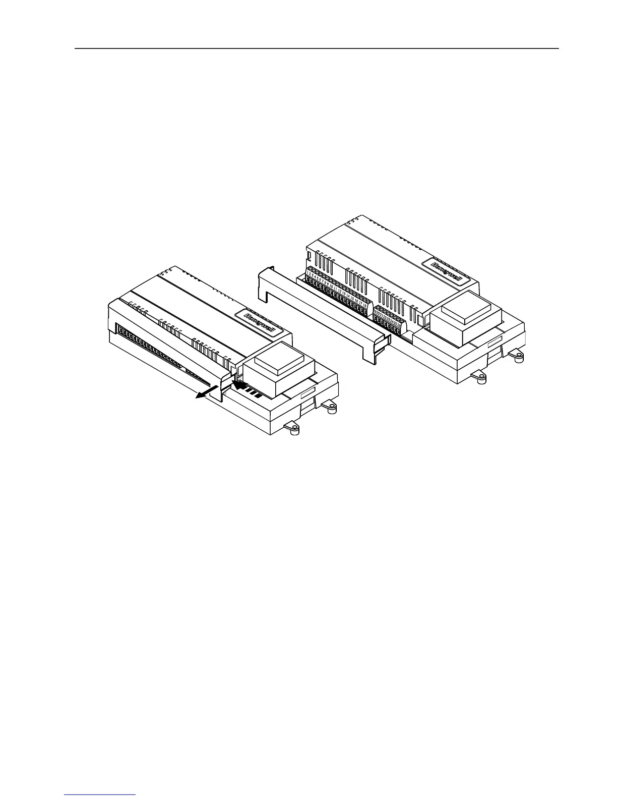
Wiring Details
Connections to the FCU controllers are made at two terminal
blocks protected by a plastic cover. W7752D and F models
have two additional terminals on terminal block 2 for electric
reheat connections. Fig. 4 shows removal of the terminal
block cover.
Use a minimum wire size of 20 AWG (0.5 mm
2
) for all
input/output connections. Use a minimum of 16 AWG
(1.5 mm
2
) for electric reheat output connections. The
maximum length of all input/output cables and wall module
interface cables is 65 ft (20 m). The maximum length for fan
power switching cables is 3 1/2 ft (1 m).
Fig. 6 illustrates the terminal assignments of the controllers.
Table 1 lists Triac output assignments for various actuator
types. Refer to job drawings for specific wiring diagrams.
IMPORTANT
Screw-type terminal blocks are designed to accept
no more than one 14 AWG (2.5 mm
2
) conductor.
Multiple wires that are 14 AWG (2.5 mm
2
) can be
connected using a wire nut. Include a pigtail with this
wire group and attach the pigtail to the individual
terminal block.
Fig. 4. Terminal cover removal
Wire to the terminal blocks as follows:
1. Strip 1/2 in. (13 mm) insulation from the conductor.
2. Insert the wire in the required terminal location and
tighten the screw to complete the termination.
3. If two or more wires are being inserted into one terminal
location, twist the wires together before inserting them.
IMPORTANT
When two or more wires are to be attached to the
same terminal, be sure to twist them together.
Deviations from this rule can result in improper
electrical contact. See Fig. 5. Local wiring codes
may take precedence over this recommendation.
 Loading...