EasyManua.ls Logo

Honeywell WV8840A - User Manual

Honeywell WV8840A
8 pages
Print Icon
To Next Page IconTo Next Page
Loading...
INSTALLATION INSTRUCTIONS
69-2247-05
WV8840A Water Heater Controls
APPLICATION
The WV8840A Water Heater Control is designed for use
in Standing Pilot applications using an immersion well for
water temperature sensing. All models of WV8840A
include an integrated NTC temperature sensor.
The WV8840A is powered from a thermopile heated by
the standing pilot flame. CS8840 pilot assemblies are
designed for use with this control.
The immersion well for sensing water temperature has
matched NTC thermistor sensors. These sensors
provide the fail-safe mechanism through which the
WV8840A can provide both accurate water temperature
control as well as water temperature limit (Temperature
Cut-Out [TCO]) function.
SPECIFICATIONS
IMPORTANT
WV8840A controls provide direct replacement
only.
Pressure Regulator: The outlet pressure regulator
setting is shown on the product label.
Inlet Pressure Range:
See appliance rating plate for inlet pressure range
recommendation.
1/2 PSI (14.0 in. w.c.) maximum inlet pressure allowed
for proper operation.
Body Pattern: 90 degrees with 1/2 in. inlet and 1/2 in.
inverted flare outlet.
Mounting: Mounting in upright position only.
Control Input:
Voltage Minimum: 350 mV dc, open circuit.
Voltage Maximum: 850 mV dc, open circuit.
Capacity: See Table 1.
Regulation Range:
Natural Gas:
Minimum: 30,000 Btuh.
Maximum: 85,000 Btuh.
Ambient Temperature Range: 32°F to 150°F
(0°C to 66°C)
Operating Range: 0°F to 150°F (-18°C to 66°C)*
Storage Range: -40°F to 150°F (-40°C to 66°C)
* Valve will operate at 0°F (-18°C) but valve characteris-
tics can not be guaranteed until ambient temperature
reaches 32°F (0°C).
Humidity: 95% non-condensing at 104°F (40°C)
Approvals:
This device is certified by Canadian Standards Associa-
tion (CSA) to the following standards:
ANSI Z21.20
ANSI Z21.23
ANSI Z21.78
ANSI Z21.87
CAN/CSA-C22.2 No. 199-M89
CAN1-6.6-M78
CSA 4.6
CSA 6.20
Accessory Parts:
Pilot Assembly CS8840

Questions and Answers

Summary

Application

Installation Instructions

Specifications

Planning the Installation

Frequent Cycling

Describes control wear with frequent appliance cycling and recommends monthly checkout.

Water or Steam Cleaning

Advises protecting the control from water or steam during cleaning procedures.

High Humidity or Dripping Water

Warns against water drip and high humidity causing corrosion and failure.

Corrosive Chemicals

Explains corrosive chemicals can cause failure; protect control from contact.

Dust or Grease Accumulation

Notes dust/grease can cause malfunction; suggests covers for protection.

Heat

Warns against excessive temperature; advises insulation and air circulation.

Flow Capacity & Pressure Drop

Details the flow capacity and pressure drop characteristics of the WV8840A control.

Installation

Install Control to Water Tank

Connect Gas Supply

Details connecting the gas supply, emphasizing safety and proper procedures.

Wiring

Fill Tank

Pilot Gas and Lighting Procedure

Turn on Main Burner

Perform Gas Leak Test

Check the gas input and burner flow rate

Maintenance

Troubleshooting

Troubleshooting With Status Indicator Assistance

Guide for diagnosing issues using the control's status indicator light.

Troubleshooting Without Status Indicator Assistance

Thermopile Output Check

Procedure to test the thermopile's voltage output for proper operation.

Instructions to the Homeowner

Stop: Read the Warnings Above

Turning Off the Appliance

Complete Shutdown

Instructions for completely shutting down the appliance and control.

Overview

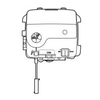
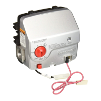
The Honeywell WV8840A Water Heater Control is designed for use in standing pilot applications, utilizing an immersion well for accurate water temperature sensing. All models of the WV8840A incorporate an integrated NTC temperature sensor. The control is powered by a thermopile heated by the standing pilot flame, and is specifically designed for use with CS8840 pilot assemblies. The immersion well, equipped with matched NTC thermistor sensors, provides a fail-safe mechanism for precise water temperature control and a water temperature limit (Temperature Cut-Out [TCO]) function. This ensures both accurate temperature regulation and safety.

Important Technical Specifications:

  • Control Input:
    • Voltage Minimum: 350 mV dc, open circuit.
    • Voltage Maximum: 850 mV dc, open circuit.
  • Regulation Range:
    • Natural Gas:
      • Minimum: 30,000 Btuh.
      • Maximum: 85,000 Btuh.
  • Ambient Temperature Range: 32°F to 150°F (0°C to 66°C).
  • Operating Range: 0°F to 150°F (-18°C to 66°C). Note that valve operation is guaranteed at 0°F (-18°C), but valve characteristics are not guaranteed until the ambient temperature reaches 32°F (0°C).
  • Storage Range: -40°F to 150°F (-40°C to 66°C).
  • Humidity: 95% non-condensing at 104°F (40°C).
  • Pressure Regulator: The outlet pressure regulator setting is indicated on the product label.
  • Inlet Pressure Range: Refer to the appliance rating plate for recommendations. A maximum inlet pressure of 1/2 PSI (14.0 in. w.c.) is allowed for proper operation.
  • Body Pattern: 90 degrees with 1/2 in. inlet and 1/2 in. inverted flare outlet.
  • Mounting: Upright position only.
  • Gas Capacity Conversion (WV8840A):
    • Natural Gas:
      • 30 kBTU/hr: 1.43 in. w.c. pressure drop.
      • 50 kBTU/hr: 1.47 in. w.c. pressure drop.
      • 75 kBTU/hr: 1.54 in. w.c. pressure drop.
    • LP Gas:
      • 30 kBTU/hr: 0.91 in. w.c. pressure drop.
      • 50 kBTU/hr: 0.94 in. w.c. pressure drop.
      • 75 kBTU/hr: 0.97 in. w.c. pressure drop.

Usage Features:

  • Installation: The WV8840A is mounted on the outside of the water heater tank. Proper installation requires screwing the assembly into the spud until the bracket is square, applying a maximum torque of 31 ft-lbs plus one turn. All piping must comply with local codes and ordinances or with the National Fuel Gas Code (ANSI Z223.1 NFPA No. 54). A sediment trap must be installed in the gas supply line to prevent contamination of the ignition system control. Use a moderate amount of good quality pipe compound on pipe threads, leaving two end threads bare, and avoid pipe dope on the outlet. Maximum torque on the inlet is 40 ft-lbs, and on the outlet is 30 ft-lbs.
  • Wiring: Follow appliance manufacturer instructions. All wiring must comply with applicable electrical codes and ordinances.
  • Filling the Tank: Refer to the appliance manufacturer's instructions to fill the tank with water.
  • Pilot Gas and Lighting Procedure:
    1. Turn the device knob to "Pilot," push down, and hold. The pilot valve opens, allowing gas to flow. Allow approximately 5 minutes of purge time for every 10 feet of 1/2-in. pipe with 5 in. w.c. pressure if the gas pipe is full of air.
    2. Depress the piezo igniter to light the pilot flame and hold the knob until the status indicator starts to blink (approximately 30 seconds), indicating the pilot is held by electronics. The LED should blink once every three seconds.
    3. Release the knob and turn to the desired temperature setting. The burner will come on if the water temperature is significantly below the setpoint, and the LED will begin to strobe every three seconds.
    4. Allow one minute for the thermopile to cool before re-lighting the pilot.
  • Turning on Main Burner: Follow manufacturer instructions or turn up the temperature at the setpoint knob.
  • Gas Leak Test: Paint pipe connections upstream of the water heater control with a rich soap and water solution. Bubbles indicate a gas leak. If a leak is detected, tighten the pipe connection. With the burner in operation, paint pipe joints (including adapters) and the control inlet and outlet with soap and water solution. Do not spray soap and water solution on the WV8840A housing.
  • Checking Gas Input and Burner Flow Rate: Check the full rate manifold pressure against the appliance nameplate. The water heater control full rate outlet pressure should match this rating. With the burner operating, check the flow rate using the meter clocking method or check pressure using a manometer connected to the outlet pressure tap.
  • Troubleshooting with Status Indicator: The control provides visual status indicator assistance. Error codes are displayed by counting the number of flashes of the status indicator after a three-second pause. A single flash (with the setpoint knob in PILOT position) indicates normal operation. Flash codes are displayed with a three-second delay between cycles. A continuous solid light indicates system shutdown when the knob is turned from a temperature setting to OFF.
  • Thermopile Output Check: Turn the device knob to OFF, disconnect thermopile leads. Turn the device knob to PILOT, hold down the knob to light the pilot burner for five or more minutes. Check thermopile output with a voltmeter; it should be at least 350 mV. Connect a 3.6 ohm resistor between the thermopile leads; the voltage should be at or higher than one half of the open circuit voltage. The flame must envelop the thermopile at the Hot Junction (3/8 in. below tip).

Maintenance Features:

  • Regular Checkout: The maintenance program should include regular checkout of the control as outlined in the Startup and Checkout section, and the control system as described in the appliance manufacturer literature.
  • Maintenance Frequency: Determined individually for each application. Appliances that cycle 10,000 times annually should be checked monthly. Intermittent use appliances should be checked before shutdown and again before the next use. Systems where unexpected shutdown would be costly should be checked more often.
  • Environmental Considerations: In dusty, wet, or corrosive environments, the system should be checked more often as these conditions can cause rapid deterioration.
  • Replacement Criteria: The system should be replaced if it does not perform properly on checkout or troubleshooting, if it has likely operated for more than 150,000 cycles, or if the control is wet or shows signs of having been wet.
  • Cleaning: Do not attempt to take apart or clean the gas valve inside the WV8840A control, as improper cleaning or reassembly can cause gas leakage.
  • Protection from Contaminants: Heavy accumulations of dust or grease can cause malfunction. Provide covers for the control to limit contamination where applicable. Avoid contact with corrosive chemicals.
  • Protection from Water/Steam: If the control gets submerged in water, replace it. If the appliance is likely to be cleaned with water or steam, protect (cover) the control and wiring from water or steam flow. Mount the control high enough above the bottom of the cabinet to prevent it from getting wet during normal cleaning procedures.
  • Protection from High Humidity/Dripping Water: Never install an appliance where water can drip on the control. In humid atmospheres, ensure adequate air circulation around the control to prevent condensation and regularly check the system.
  • Protection from Heat: Ensure the maximum ambient temperature at the control does not exceed its rating. If the appliance operates at very high temperatures, use insulation, shielding, and air circulation as necessary to protect the control.

Honeywell WV8840A Specifications

General IconGeneral
BrandHoneywell
ModelWV8840A
CategoryController
LanguageEnglish

Related product manuals