EasyManua.ls Logo

Honeywell WEB-600E User Manual

Honeywell WEB-600E
20 pages
To Next Page IconTo Next Page
Page #1 background imageLoading...
Page #1 background image
INSTALLATION INSTRUCTIONS
62-0433-01
WEB-600E and CP-600E Network
Controllers
ABOUT THIS GUIDE
This document covers installation instruction of Honeywell's
WEB-600E controller. It assumes that you are an engineer,
technician, or service person who is performing control
system installation. Instructions in this document apply to the
following products:
NOTE: Not covered in this document is the WEBs-AX
software installation and configuration required
for a fully functioning unit. Refer to the JACE
Niagara AX Install and Startup Guide for this
information.
In addition, the installation of controller expan-
sion options are covered in separate documents.
See Related Documentation, and also the section
“About Expansion Options” on page 5.
The Content of this document equally applies to
CP-600E product.
Related Documentation
For more information on configuring and using the WEB-600E
controller, refer to the following documents:
JACE NiagaraAX Install and Startup Guide
JACE Data Recovery Service (SRAM Support) -
Engineering Notes
IO-16-H Installation and Configuration Guide
IO-34-H Installation and Configuration Guide
Various option card installation documents, such as:
NPB-LON Option Install Sheet
NPB-2X-485 Option Install Sheet
NPB-RS232 Option Install Sheet
NPB-GPRS Modem Option Install Sheet
NPB-ZWAVE Option Card Install Sheet
NiagaraAX Ndio Guide
NiagaraAX User Guide
PREPARATION
Unpack the controller and inspect the package contents for
damaged or missing components. If damaged, notify the
appropriate carrier at once and return any damaged
components for immediate repair or replacement. See
“Returning a Defective Unit” on page 17
Included in this Package
Material and Tools Required
Included in this Package
Included in this package you should find the following items:
a WEB-600E or a CP-600E controller.
•This WEB-600E and CP-600E Network Controllers, Part
Number 62-0433_A Rev 9/12
a hardware bag containing the following items:
One (1) grounding wire, with quick-disconnect 0.187"
female connector.
Material and Tools Required
The following supplies and tools are typically required for
installation:
A suitable power module, as one of the following types:
NPB-PWR-H: 24Vac or 24Vdc, in-line, DIN mount
capable, with grounding wire
NPB-PWR-UN-H: 120–240Vac, in-line, DIN mount
capable, with grounding wire
NPB-WPM-US: External wall mount power adapter
(input 90-254 Vac, 50-60 Hz, output 15Vdc, 1A)
NOTE: Using an NPB-PWR-H power module provides
the widest operating temperature range. See
“Environmental Requirements” on page 3.
Model Description
WEB-600E,
WEB-600E-USA,
CP-600E,
CP-600E-USA
DIN mount WEB-600E and CP-600E
controller, powered by one of the two
separate plug-in power supply
modules, or by wall mount AC power
adapter. Controller supports optional
I/O expansion modules and internal
communications option cards.
NPB-PWR-H 24Vac/dc input/15Vdc output power
supply module, DIN mountable.
NPB-PWR-UN-H 120–240Vac universal input/15Vdc
output power supply module, DIN
mountable.
NPB-WPM-US External wall mount power adapter
(input 90-254 Vac, 50-60 Hz, output
15Vdc, 1A)
Question and Answer IconNeed help?

Do you have a question about the Honeywell WEB-600E and is the answer not in the manual?

Honeywell WEB-600E Specifications

General IconGeneral
ModelWEB-600E
TypeController
Input Voltage24 VAC/VDC
Number of Inputs16
CommunicationEthernet, Serial
Ethernet Ports1
Power Supply24 VAC/VDC
Humidity Range10% to 90% non-condensing
Communication ProtocolBACnet, Modbus
SeriesWEB Series
Dimensions15.2 cm x 14.0 cm x 6.4 cm (6.0 in x 5.5 in x 2.5 in)

Summary

Installation Instructions

Preparation and Unpacking

Unpack and inspect controller package contents for damage or missing items.

Package Contents and Required Items

Lists items that should be included in the controller package.

Tools and Materials Needed

Lists supplies and tools typically required for controller installation.

Safety and Precautions

General Safety Warnings and Cautions

Alerts and advice for safe operation, covering potential hazards.

Static Discharge Prevention

Precautions to prevent damage to electronic components from static discharge.

Battery Safety and Handling

Cautions regarding the handling and use of the NiMH battery pack.

Environmental and Disposal Information

WEEE information for electronic product recycling.

Mounting the Controller

Mounting Location Considerations

Notes on clearance, accessibility, and environmental factors for mounting.

Environmental Operating Requirements

Details ambient operating temperature and humidity limits for the controller.

Physical Mounting Guidelines

Information on physically mounting the controller unit.

DIN Rail Mounting Procedures

Mounting the Controller on DIN Rail

Step-by-step instructions for DIN rail installation.

Removing Controller from DIN Rail

Procedures for detaching the controller from a DIN rail.

Controller Components and Expansion

Cover Removal and Replacement

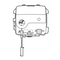
How to remove and replace the controller's cover to access internal components.

Controller Board Layout

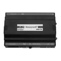
Identification of controller features, LEDs, and ports on the main board.

Expansion Options Overview

Introduction to field-installable expansion options for the controller.

Option Card Installation Safety

Option Card Installation Warning

Crucial safety warning about powering off the controller before installing/removing cards.

Installing Option Cards and Modules

Installing an Option Card

Step-by-step guide for installing an option card into the controller.

Accessory Module Connection

Information on accessory modules and how they connect to the controller.

Accessory Module Installation Warning

Crucial safety warning about powering off before handling accessory modules.

Wiring and Power Supply

Grounding Connections

Importance and procedure for connecting the earth ground lug for protection.

Power Supply Options

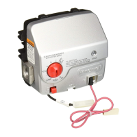
Details on approved 15 Vdc power sources and connections for the controller.

NPB-PWR-H Power Module

Specifics for using the NPB-PWR-H power module to power the controller.

Power Module Wiring

NPB-PWR-H Module Wiring

Wiring connections for the NPB-PWR-H power module.

NPB-PWR-UN-H AC Power

Details for powering the controller from AC line power using NPB-PWR-UN-H.

NPB-PWR-UN-H Power Warnings

Warnings for AC power connections to the NPB-PWR-UN-H module.

Communication and Power Ports

NPB-WPM-US Adapter Use

Using the NPB-WPM-US wall mount AC adapter for controller power.

Communications Port Overview

Overview of controller communication ports: Ethernet and Serial.

Ethernet Port Configuration

Details on the controller's LAN1 (primary) and LAN2 (secondary) Ethernet ports.

Serial Port Configuration

Details on the controller's RS-232 (COM1) and RS-485 (COM2) serial ports.

RS-485 Communications

RS-485 Port Pinout

Pinout reference for the controller's RS-485 serial port.

RS-485 Bias Functionality

Need for and explanation of RS-485 bias to improve communication reliability.

Adding RS-485 Bias

Steps to implement RS-485 bias by adding shorting blocks.

RS-485 Bias Installation Safety

Safety precautions required before modifying the controller for RS-485 bias.

Controller Internal Access and Bias

Controller Disassembly Steps

How to carefully disassemble the controller to access internal components.

Installing RS-485 Bias Shorting Blocks

Procedure for installing shorting blocks to add RS-485 bias.

Controller Reassembly Steps

How to reassemble the controller after internal modifications.

Initial Power Up and Backup

Applying Power and Initial Checkout

How to apply power and check controller status using LEDs.

Backup Configuration Methods

Methods to preserve station data during power quality events.

SRAM and NiMH Battery Backup

Using on-board SRAM and the optional NiMH battery for data backup.

Status Indicators and Maintenance

Status LED Descriptions

Detailed explanation of all status LEDs on the controller.

Controller Maintenance Topics

Overview of controller maintenance tasks.

Controller Cleaning Procedures

How to clean the controller unit.

NiMH Battery Installation and Maintenance

Instructions for installing and maintaining the optional NiMH battery.

Battery Management and Disposal

NiMH Battery Maintenance Details

Information on NiMH battery life expectancy, charging, and periodic testing.

Battery Disposal and Warnings

Proper disposal of used NiMH batteries and associated warnings.

Replacement Parts and Units

Non-replaceable and Standard Parts

Information on parts that are not field-replaceable or are standard order items.

Replacing the Controller Unit

Procedure for ordering and installing a new WEB-600E controller.

Controller Base Assembly Replacement

Detailed steps for replacing the controller's base assembly.

Returning Defective Units

Defective Unit Return Process

General steps and requirements for returning a defective unit for credit or repair.

Regional Return Contact Information

Regional contact details for obtaining RMA numbers and return instructions.

Product Certifications and Compliance

Information on FCC, DOC, and RoHS compliance for the equipment.

CE Declaration of Conformity

Applicable EMS Standards

List of EMS standards the equipment complies with, including EMC and immunity.

Tab Mounting Dimensions

Tab Mounting Diagram and Notes

Explains tab mounting details, dimensions, and recommendations.

Related product manuals