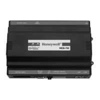
WEB-8000 CONTROLLER
31-00091—02 2
Precautions
The following are warnings relating to the installation and
start-up of the controller.
To reduce the risk of fire or electrical shock, install
in a controlled environment relatively free of
contaminants.
To comply with FCC and Industry Canada RF
exposure limits for general population/
uncontrolled exposure, the antenna(s) used for this
transmitter must be installed to provide a
separation distance of at least 20 cm from all
persons and must not be co-located or operating in
conjunction with any other antenna or transmitter.
Remove all power to controller before attaching
(plug in) or detaching (unplug) any option
module, to prevent possible equipment damage.
Removal of the controller’s cover is not required.
No configurable or user-serviceable items (such as
jumpers or a battery) require cover removal.
Disconnect power before installation or servicing
to prevent electrical shock or equipment damage.
To reduce the risk of fire or electrical shock, install
in a controlled environment relatively free of
contaminants.
MOUNTING
Mount the controller in a location that allows clearance for
wiring, servicing, and module removal.
Environmental requirements
NOTE: This product is for indoor use only, altitude to
2,000m (6,562 ft.).
Ambient conditions must be within the range of:
• Operating Temperature: -20°C to 60°C (-4°F to 140°F).
Storage Temperature: -40°C to 85°C (-40°F to 185°F).
• Relative humidity: 5% to 95% non-condensing.
Pollution Degree 3
• Supply (mains) voltage requirements are as follows:
— Allowable voltage fluctuation to ±10%.
NOTE: Horizontal mounting is strongly recommended,
to achieve maximum heat dissipation and meet
the operating temperature upper limit. Any other
mounting orientation reduces this upper limit.
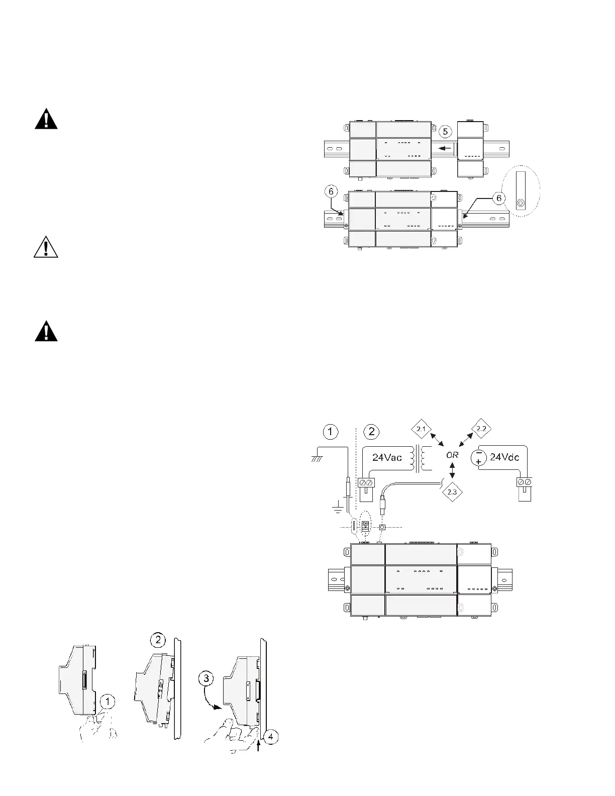
Mounting on DIN rail
1. Pull the controller’s locking clip down.
2. Tilt the controller to hook over the DIN rail.
3. Push down and in on the unit, fastening to the rail.
4. Push the locking clip up to secure.
5. Mount any option module onto the DIN rail in the
same way.
Slide the module firmly into the controller’s connector
to seat. Repeat for other modules as needed
(4 maximum).
6. Secure both ends of the final assembly with DIN rail
end-clips provided by the DIN rail vendor.
WIRING
Earth ground and power
Earth grounding provides protection from electrostatic
discharge or other forms of EMI.
Fig. 3. Earth ground and power options.
NOTES: Depending on power source used (see Fig. 3):
— 2.1 (AC): Dedicated 24V transformer required,
with neither side of the transformer secondary
tied to ground.
— 2.2 (DC): Polarity is unimportant (uses
onboard diode bridge), with neither leg tied to
ground.
— 2.3 (Wall-mount AC adapter, WPM-8000)
instead of wiring 24V to 2-position connector.
M35798
M35799

 Loading...