WV8860C WATER HEATER CONTROLS
34-00019—03 4
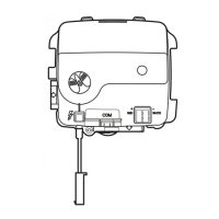
Fig. 4. Use a moderate amount of pipe compound.
Table 2. NPT pipe thread length (in.).
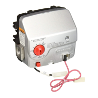
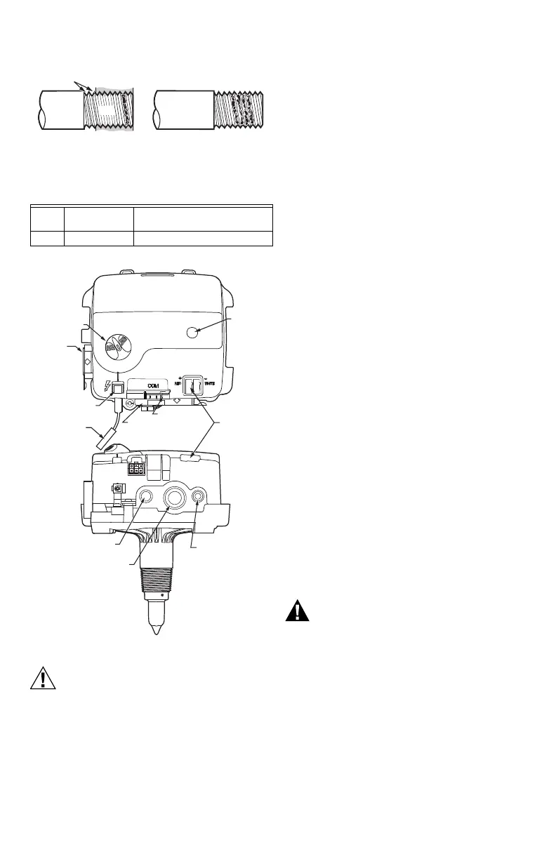
Fig. 5. Water heater controls and connections.
Contamination Hazard.
Can cause equipment malfunction.
Do not use thread tape sealants to seal the gas
supply to the control.
a. Use a pipe compound to seal the connection.
b. Use only ANSI-approved compounds.
Wiring
Follow the wiring instructions furnished by the appliance
manufacturer, if available, or use the general instructions
provided below. When these instructions differ from the
appliance manufacturer, follow the appliance
manufacturer instructions. Make sure wiring insulation
does not get cut by sharp edges.
NOTE: All wiring must comply with applicable electrical
codes and ordinances.
Connect control circuit to the water heater control using
the connections shown in Fig. 5.
Fill Tank
Refer to the appliance manufacturer’s instructions to fill
the tank with water.
Pilot Gas and Lighting Procedure
1. Start by turning the device knob to Pilot, push the
knob down, and hold in position. (The pilot valve
opens and allows gas to flow into the pilot burner.)
NOTE: If the gas pipe is full of air (new installation), it
takes a long time to purge the air through the
pilot before the pilot will light. Approximately 5
minutes of purge time is required for every 10
feet of 1/2-in. pipe with 5 in. w.c. pressure.
2. Depress the piezo igniter to light the pilot flame
and hold the knob in until the status indicator
starts to blink (approximately 30 seconds),
indicating pilot now being held by electronics.
NOTE: LED should blink once every three seconds. If
not, check the error codes in Table 3.
3. Release the knob and turn to the desired
temperature setting. The burner will come on if
water temperature is significantly below the
temperature setpoint and the LED should continue
to blink once every three seconds.
4. Allow one minute for thermopile to cool before
relighting pilot.
Turn on Main Burner
Follow the instructions provided by the manufacturer or
turn up the temperature at the setpoint knob.
Scalding Hazard.
Can cause burns, severe injury or death.
Never move the setpoint knob past the Hot
setting unless extremely hot water is desired.
Always check water temperature at the faucet
and readjust until comfortably warm to the touch.
Consider the ages and health of all who will come
in contact with heated water.
Pipe
Size
Thread Pipe
This Amount
Maximum Depth Pipe can be
inserted into Control
1/2 3/4 1/2
TWO
IMPERFECT
THREADS
IGNITION
SYSTEM
CONTROL
THREAD PIPE THE AMOUNT
SHOWN IN TABLE 2 FOR INSERTION
INTO IGNITION SYSTEM CONTROL
APPLY A MODERATE AMOUNT OF
PIPE COMPOUND ONLY TO PIPE
(LEAVE TWO END THREADS BARE).
M29771
PIPE
BOTTOM VIEW
M36634
PRESSURE
TAP
MAIN GAS
PILOT
GAS
THERMOPILE
GAS LINE
CONNECTION
PIEZO IGNITOR
SWITCH
FRONT VIEW
DEVICE
KNOB
STATUS
INDICATOR
SERIAL
COMMUNICATIONS
CHAMBER
SENSOR
IGNITOR
LEAD
 Loading...