28
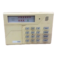
Figure 25 Schematic Diagram of the NRI Standby Power Supply Cable Connection
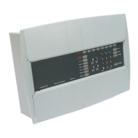
Connecting the DA Main and Standby Power Supply Cables
Connecting the Main Power Supply Cable
1. Strip off the wire jacket of one end of the prepared standby power supply cable by 20mm and
connect the cable to the main power supply wiring terminal, as shown below.
2. Tighten the screws, and cover the power supply interface set.
3. Insert the wiring terminal of the installed power supply cable into the main power supply input
port of the DA, and tighten the screws at both ends.
4. Insert the other end of the main power supply cable into the main power supply equipment.
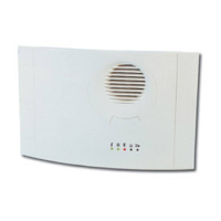
Connecting the Standby Power Supply Cable
1. Strip off the wire jacket of one end of the prepared standby power supply cable by 20mm and
connect the cable to the standby power supply wiring terminal, as shown below.
 Loading...