Do you have a question about the Honeywell MK XXII and is the answer not in the manual?
Provides information about the Enhanced Ground Proximity Warning System (EGPWS) with respect to Line Maintenance Operations.
Manual is applicable to MK V, MK VI, MK VII, MK VIII, and MK XXII EGPWS with specific part numbers.
Lists additional EGPWS references for MK V, MK VII, MK VI, MK VIII, MK XXII models.
Purpose of EGPWS is to prevent accidents from CFIT, obstacles, or windshear. Provides aural/visual alerts.
Details various EGPWS operating modes including Excessive Descent Rate, Terrain Closure Rate, Descent After Takeoff.
Provides audio and visual alerts for excessive descent rates into terrain, with 'SINKRATE' and 'PULL-UP' enunciations.
Provides alerts for dangerously high terrain closure rates with 'TERRAIN, TERRAIN' and 'PULL-UP' enunciations.
Alerts for excessive altitude loss after takeoff or go-around. Enunciates 'DON'T SINK'.
Alerts for unsafe terrain clearance based on phase of flight, height, speed. Uses 'TOO LOW TERRAIN/GEAR/FLAPS'.
Alerts for excessive glideslope deviation with 'GLIDESLOPE' enunciation.
Provides optional aural callouts for altitude, minimums, and bank angle. No alert lights.
Callout for excessive bank angles based on altitude and aircraft type. Enunciates 'BANK ANGLE'.
Alert function for applicable rotary wing aircraft based on Radio Altitude, Pitch Attitude, etc. Enunciates 'Tail Too Low'.
Provides alerts for windshear of sufficient magnitude to be potentially hazardous to the aircraft.
Improves alert protection and expands margins at key locations by modulating envelopes.
Adds terrain clearance envelope around airport runways for CFIT protection.
Database of data records for all airport runways for coverage provided by the Terrain Database.
Monitors aircraft position to provide rapid audio/visual alerts for terrain threats.
Enhancement to terrain display, viewing terrain below aircraft emphasizing highest/lowest elevations.
Computed pseudo-Corrected Barometric Altitude for optimal EGPWS function across all flight phases.
Automatic Weather Radar tilt angle capability using aircraft altitude and terrain database.
Drives cockpit annunciators and EFIS with system status and alert annunciations.
Offers safety enhancements for aircraft with MK V/VII EGPWS, providing advisories and alerts for operations.
Offers safety enhancements for aircraft with MK V/VII EGPWS, providing advisories for unstabilized approach.
Offers safety enhancements for aircraft with MK V/VII EGPWS, providing advisories for incorrect altimeter setting.
Offers safety enhancements for aircraft with MK V/VII EGPWS, providing alerts for improper flap setting before takeoff.
Offers safety enhancements for aircraft with MK V/VII EGPWS, providing alerts for landing position awareness.
Offers safety enhancements for Boeing 737NG aircraft with MK V EGPWS, providing aural alert for low airspeed.
Describes two different caution/warning lamp illumination formats for EGPWS alerts.
EGPWS is an 'on-condition' only maintenance system. No scheduled maintenance required.
Details system status indications during INOP conditions, including TERR INOP, GPWS INOP.
EGPWC contains extensive Built-In-Test (BIT) capability to verify warning computer and interface signal sources.
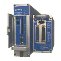
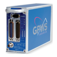
Describes indicators and user interfaces on the EGPWC front panel for troubleshooting.
Explains the yellow External Fault, green Computer OK, and red Computer Fail LEDs.
Provides a Self-Test switch for activating Self-Test features.
Front panel headphone jack for use during Self-Test.
PCMCIA card slot for MK V/VII, or external interface for MK VI/VIII/XXII for data.
Provides communication support for maintenance and test functions via RS-232/422.
Supports manually operated Self-Test sequence indicating system operational status.
Methods to identify system/subsystem faults. Do not remove EGPWC until fault is isolated.
Table showing recommended maintenance action based on front panel LED status.
Provides an overview of the current operational capability of EGPWS. Divided into Preamble, Short, and Long tests.
First step of Self-Test checking for configuration errors before Short/Long Level 1 Self-Test.
Provides a Go/No Go confidence test indicating EGPWS functionality and outputs.
Initiated by pressing Self-Test until voices start. Enunciates all configured alerts following Short Level 1.
Provides enunciation of all faults existing at time of test request. Differentiates internal/external faults.
Lists internal fault messages and probable maintenance response (e.g., ROM FAILED, RAM FAILED).
Lists external faults indicating problems with sensors, systems, or wiring (e.g., ARINC 429 Bus Fault).
Enunciates EGPWC configuration information like Part Number, Software Version, Aircraft Type.
Provides enunciation of faults recorded over the last 10 flight legs.
Provides enunciation of alerts (cautions and warnings) recorded over the last 10 flight legs.
Provides enunciation of discrete input status changes for verification of function and wiring.
Three Radio Altitude validity flags used by EGPWS for ARINC 552 or ALT 55 Radio Altimeter inputs.
Input supplied by landing gear or selector handle position-sensitive switch. Indicates landing gear status.
Input supplied by landing gear or selector handle position-sensitive switch. Indicates landing gear status.
Input from Flap or Flap selector handle switch. Indicates landing flaps selected or not.
Input from Flap or Flap selector handle switch. Indicates landing flaps selected or not.
Up to four flap position discretes supplied from flap selector handle switch. Indicate flap position selected.
Supplied by momentary actuated cockpit self-test switch. Indicates self-test status.
Requires two discretes to activate Steep Approach. One enabled for use, one selected in flight.
Steep Approach Enabled discrete. Indicates Steep Approach Enabled or Disabled status.
Steep Approach Selected discrete. Indicates Steep Approach Selected or Not Selected status.
Input from ILS/VOR Mode Selector. Indicates ILS tuned or VOR tuned status.
Input from ILS/VOR Mode Selector. Indicates ILS tuned or VOR tuned status.
Two Glideslope Validity Discretes for ARINC 547 Glideslope Receiver input. Indicate Valid or Invalid.
Switch for inhibit of Glideslope mode. Indicates Glideslope Inhibit or Not Inhibit.
Switch for inhibit of Glideslope mode. Indicates Glideslope Inhibit or Not Inhibit.
Cockpit Glideslope mode manual inhibit switch. Indicates Glideslope is canceled or enabled.
Decision Height Bug switch. Indicates Less than or Greater than Decision Height.
Mode 6 low volume select switch. Indicates Low Volume Select or Normal Volume.
Mode 6 Altitude callouts enable switch. Indicates Callouts Enabled or Disabled.
Discrete inhibits audio/visual except Windshear. Controls suppression based on aircraft type.
Discrete inhibits audio/visual except Windshear. Controls suppression based on aircraft type.
AOA validity discretes for AOA Indication System or Stall Warning Computer. Indicate Fail or Not Fail.
Cockpit manual switch for display selection. Indicates TAD activated or canceled.
Switch for inhibit of Terrain Awareness & TCF functions. Enunciates 'Terrain Inhibited' if disabled.
Switch for activating Simulator Reposition. Presets EGPWS to match simulator initial conditions.
WXR On/Off switch input. Indicates Radar turned on or off.
Localizer validity discretes for ARINC 547 Localizer Receiver input. Indicate Valid or Invalid.
Attitude validity discretes for Attitude sensor. Indicate Valid or Invalid.
Airspeed validity discrete for Airspeed sensor. Indicates Valid or Invalid.
Barometric Altitude Rate validity discretes for barometric rate sensor. Indicate Valid or Invalid.
Indicates Accelerometers are in Self-Test mode. Shows Self-Test Active or Inactive.
Longitudinal Acceleration validity discrete for Acceleration sensor. Indicates Valid or Invalid.
Normal Acceleration validity discrete for Acceleration sensor. Indicates Valid or Invalid.
Magnetic Heading validity discrete for Magnetic Heading sensor. Indicates Valid or Invalid.
AOA Vane Heater Discrete for indication of vane heat for flight history recording.
PLI deselect switch discretes to deactivate PLI select relays to remove EGPWS PLI indication.
Autopilot Disconnect discretes for indication that Autopilot has been disconnected.
Tactical Select discrete for indication that Tactical Select switch has been pressed.
Altitude Alert discrete for indication that Altitude Alert is selected.
Corrected Barometric Altitude Validity Discrete to determine when Corrected Altitude input is invalid.
Flap Override Discrete to determine when Flap Override has been selected.
Weight On Wheels Discrete to determine if aircraft is on the ground.
Discrete inhibits audio/visual except Windshear, Terrain Awareness and TCF.
Discrete for enabling RAAS functionality.
Discrete for inhibiting RAAS functionality, also inhibits Long Landing Monitor and Takeoff Flap.
Discrete for enabling Stabilized Approach Monitor functionality.
Discrete for inhibiting Stabilized Approach Monitor functionality.
Discrete for inhibiting Low Airspeed Monitor functionality.
Normal maintenance activities follow standard industry practices. Includes database updates, history download, programming.
EGPWS uses databases for enhanced functions. These are periodically updated as new data becomes available.
Honeywell strives to improve databases. Updates released when sufficient new data is available.
Database loaded via PCMCIA card (MK V/VII) or Smart Cable (MK VI/VIII/XXII).
EGPWC records detected faults and data. Flight history can be downloaded via PCMCIA interface for analysis.
Procedure to obtain a Flight History Download (PCMCIA) Card.
Step-by-step procedure for downloading flight history data from EGPWC using PCMCIA card.
Contact Honeywell Technical Operations for transcription of Flight History Download Card data.
Accomplished using WinVIEWS on a PC connected to EGPWC via RS-232 interface.
Reprogramming the Configuration Module is similar to programming, allowing individual categories to be changed.
The EGPWS does not require any servicing.
Procedures for removing and installing the EGPWC unit.
Steps to remove the EGPWC unit from the aircraft.
Steps to install the EGPWC unit into the aircraft.
Refer to Installation Design Guide for Configuration Module illustrations.
Steps to remove the Configuration Module from the P2 connector.
Steps to install the Configuration Module to the P2 connector.
Refer to appropriate EGPWS aircraft wiring and mechanical drawings.
The EGPWS does not require any adjustments.
Line maintenance testing for EGPWS consists of functional verification.
System inspected for integrity and checked for wear/tear during routine aircraft maintenance.
EGPWS does not require cleaning or painting. Performed by authorized repair facility.
No on-aircraft repairs. Unit removed and replaced if problem found, routed to repair facility.
WinVIEWS is a software tool for monitoring and testing EGPWC. Assists in determining signal/scaling and status.
Guidance on using self-test, WinVIEWS, and front panel LEDs for troubleshooting.
Details RAAS maintenance messages and associated notes for Self-Test Level 1 and 3.
Details Stabilized Approach Monitor messages for Self-Test Levels 1, 2, and 3.
Details Altimeter Monitor messages for Self-Test Levels 1, 2, and 3.
Details Takeoff Flap Configuration Monitor messages for Self-Test Levels 1, 2, and 3.
Details Long Landing Monitor messages for Self-Test Level 1 and 3.
Details Low Airspeed Monitor messages for Self-Test Levels 1 and 3.
| Brand | Honeywell |
|---|---|
| Model | MK XXII |
| Category | Security System |
| Language | English |