Do you have a question about the Honeywell Gamewell-FCI MS-95 and is the answer not in the manual?
| Model | MS-95 |
|---|---|
| Battery Backup | Yes |
| Operating Temperature | 32°F to 120°F (0°C to 49°C) |
| Brand | Gamewell-FCI by Honeywell |
| NAC Circuits | 2 |
| Voltage | 120 VAC |
| Relative Humidity | Up to 93% non-condensing |
| Compliance | CSFM, FM |
Specifies the operational temperature range for the detector.
Specifies the storage temperature range for the detector.
Specifies the humidity range for the detector.
Specifies the acceptable air velocity range for the detector.
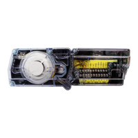
Details the physical dimensions of the D4120 detector.
Outlines electrical specifications including power supply and current.
Lists the ratings for alarm initiation and auxiliary contacts.
Details current requirements for connected accessories at 24 VDC.
Specifies ratings for supervisory contacts.
Read guide for proper use, spacing, placement, zoning, wiring, and special applications.
Explains how the detector senses smoke and initiates alarms.
Lists key features like dual sensors, cover missing signal, and sampling tubes.
Lists items included in the duct smoke detector kit.
Ensures air velocity is within parameters for proper detector function.
Guides on selecting optimal duct location and configuration.
Provides instructions for drilling holes based on mounting configuration.
Guides on choosing the correct sampling tube length for duct width.
Details the procedure for installing the sampling tube into the detector.
Explains permissible modifications for non-standard duct widths.
Covers remote mounting of sampling and exhaust tubes.
Describes how to measure differential pressure for air flow.
Details a specific test for verifying airflow at low speeds using a transmitter.
General guidelines for proper wiring installation.
Instructions for wiring a second sensor module.
Explains the function of the unit's dip switches for configuration.
Describes how LEDs indicate the detector's status.
Key considerations for interconnecting multiple detectors.
Verifies dip switch settings match desired configuration.
Instructions on applying power to the detector.
Guidance on performing checks for standby and trouble states.
Explains how to verify sensor sensitivity through LED indications.
Step-by-step guide for cleaning the detector.
Detailed steps for disassembling and cleaning the sensor.
Steps to reinstall the detector after cleaning.
Procedures for removing and replacing the sensor head.
Information on the remote test station accessory.
Details the multi-signaling accessory features.
Outlines the terms and conditions of the product warranty.
Overview of the addressable manual pull station and its compatibility.
How to activate and reset the manual pull station.
Lists part numbers for the pull station and related accessories.
Introduction to L-Series audible visible notification products.
Highlights features simplifying installation, like plug-in design.
Lists key features of the L-Series devices.
Specifies compatible backboxes for mounting.
Details the Sync Circuit Module and its function.
Lists UL maximum current draw for strobes.
Details compliance and features of the strobe component.
Details compliance and features of the horn strobe component.
Lists part numbers for ceiling horn strobes.
Lists part numbers for ceiling strobes.
Lists available accessories for the L-Series.
Explains the PID-95P as an interface for dry-contact devices.
Describes how the PID-95 connects and monitors devices.
Details the DIP switch setting for device address and interrupt.
How the PID-95 serves as an interface for monitoring points.
Lists part numbers for PID-95P and PID-95 devices.
Lists key features of the PSN series power supplies.
Provides a general description of the notification power supplies.
Details the physical dimensions and enclosure specifications.
Specifies power input requirements and current draw.
Details NAC output capabilities and battery charging.
Outlines contractor responsibilities and panel capabilities.
Explains Quadrasync and input tracking synchronization.
Explains the RCE-95 as an interface for building functions.
Describes how the RCE-95 monitors devices and circuits.
Details setting the RCE-95 address via DIP switch.
Lists key features like Form-C contacts and LED indication.
Specifies mounting in a standard electrical backbox and visibility.
Lists part numbers for the RCE-95 and optional RCD.
Introduces accessories for duct detectors.
Lists available duct smoke detector accessories.
Highlights features of specific accessories like piezo annunciators.
Details operation of multi-signaling accessories.
Specifies voltage, current, temperature, and dimensions.
Lists specifications for mini-horns.
Details specifications for remote annunciators.
Lists specifications for remote test stations.
Provides specifications for multi-signaling accessories.
Visual representation of various accessories.
Lists part numbers and descriptions for accessories.


 Loading...