EasyManua.ls Logo

Honeywell Gamewell-FCI ILI-S-E3 User Manual

Honeywell Gamewell-FCI ILI-S-E3
190 pages
To Next Page IconTo Next Page
Page #1 background imageLoading...
Page #1 background image
CFI Security Inc.
1845 Northwestern, Suite B
El Paso, Texas 79925
Ph (915) 778-6061
Fax (915) 778-7046
Fire Alarm and Mass Notification
O&M Manual
TACTICAL EQUIPMENT MAINTENANCE FACILITY (TEMF)
FT BLISS EQUIPMENT MAINTENANCE FACILITIES (EMF)
FORT BLISS, TEXAS
Gamewell FCI Fire Alarm & Mass
Notification System

Table of Contents

Question and Answer IconNeed help?

Do you have a question about the Honeywell Gamewell-FCI ILI-S-E3 and is the answer not in the manual?

Honeywell Gamewell-FCI ILI-S-E3 Specifications

General IconGeneral
ModelILI-S-E3
Input Voltage24 VDC
Operating Temperature32°F to 120°F (0°C to 49°C)
Humidity Range10% to 93% non-condensing
CompatibilityGamewell-FCI

Summary

Installation Procedures

2.4 Mounting Main Sub-assemblies

Instructions for mounting primary sub-assemblies like ILI-MB-E3.

System Connections and Wiring

3.1 ILI-MB-E3 and ILI95-MB-E3 Connections

Details electrical specifications and connections for ILI-MB-E3 and ILI95-MB-E3.

3.2 ILI-MB-E3 Main Board Connections

Illustrates and details wiring connections for the ILI-MB-E3 main board.

3.3 ILI95-MB-E3 Main Board Connections

Illustrates and details wiring connections for the ILI95-MB-E3 main board.

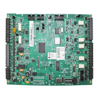
3.4 ILI-S-E3 Slave Board Connections

Details connections and wiring for the ILI-S-E3 slave board.

3.5 ILI95-S-E3 Slave Board Connections

Details connections and wiring for the ILI95-S-E3 slave board.

3.6 Address Switch Settings

Illustrates DIP switch settings for programming addresses on ILI-E3/ILI95-E3.

3.7 ANX Connections

Details connections and wiring requirements for Addressable Node Expanders (ANX).

Power Up Procedure

6.1 General Power Up Requirements

General warnings and steps for safe system power-up.

6.3 Automatic Configuration

Explains the process for automatic system configuration after power-up.

Control Panel Circuit Wiring Requirements

8.1 E3 Series Control Panel Circuit Wiring Requirements

Provides a table detailing circuit wiring requirements for the E3 Series control panel.

8.2 E3 Series Power-Limited and Non Power-Limited Diagram

Illustrates the power-limited and non-power-limited wiring configurations.

Related product manuals